In the oil and gas industry, knock out drums play a crucial role in separating liquid droplets from gas streams to prevent downstream equipment damage and improve process efficiency. However, the sizing of a knock out drum can be a complex process that involves various factors such as flow rates, pressures, and fluid properties.
In this blog post, we will study about the vertical knockout drum. We will also check the step-by-step guide to knock out drum sizing calculation along with an example problem.
Table of content:
What is a knock out drum?
Vertical knock out drum
Vertical knock out drum sizing calculation
What is a knock out drum?
A knock out drum, also known as a separator drum, is a horizontal or vertical vessel designed to separate liquid droplets from a gas stream. The gas stream enters the vessel and flows through a mist eliminator, which removes the liquid droplets and allows the gas to exit through an outlet. The liquid collects at the bottom of the vessel and is removed through a drain.
Knock out drums are commonly used in oil and gas production facilities, refining operations, and chemical processing plants to remove liquids from gas streams before they enter downstream equipment such as compressors, pipelines, or reactors.
Vertical knock out drum
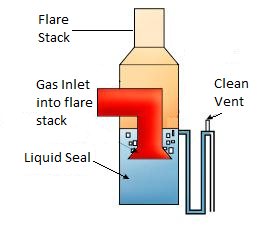
A vertical knock out drum is a type of separator vessel that is oriented vertically, with the gas and liquid flows entering and exiting from the top and bottom, respectively. The gas stream enters the top of the drum and flows downward through a mist eliminator, which removes the liquid droplets and allows the gas to exit through an outlet located near the top. The liquid collects at the bottom of the drum and is removed through a drain or pump.
Vertical knock out drums are commonly used in applications where space is limited, such as offshore oil and gas platforms, and where gravity can be utilized to separate the liquid droplets from the gas stream. They can be designed to handle various flowrates, pressures, and temperatures, and can be constructed from a variety of materials such as carbon steel, stainless steel, or exotic alloys.
The design of the internals of the drum, such as the mist eliminator and demister pads, is critical to achieving efficient separation of the liquid droplets from the gas stream.
Vertical knock out drum sizing calculation
Problem Statement
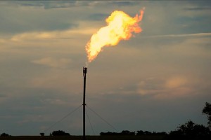
Design a vertical gas-liquid separator or a Knock Out Drum for separation of liquid droplets entrained in fuel gas flow. The liquid in this case is water and the fuel gas phase can be considered to be mostly ethane.
Flow rate of water = 18 m3/hr
Entrained Flow of fuel gas = 100 m3/hr
Operating temperature of separator = 25 0C
Operating pressure of separator = 0.2 barg (near atmospheric)
Separation efficiency required is to remove water droplets above the size of 10 microns.
Fuel gas properties can be approximately taken as properties of ethane.
Solution
Step 1
Water density at 25 0C = 994.72 kg/m3
Water viscosity at 25 0C = 0.9 cP
For fuel gas properties,
Molecular weight of ethane = 30 gm/gmole
Fuel gas density at 25 0C = 1.45 kg/m3
Fuel gas viscosity at 25 0C = 0.0069 cP
Step 2
The gas liquid separation can be modeled using Stokes law. Where gas bubble terminal velocity is expressed as,

The subscripts L and G stand for liquid phase and vapour phase respectively.
And the gas bubble diameter Dp is described in microns.
Thus, using Dp = 10 micron,
Vt = 0.0078 m/s
(It should be noted that the use of Stokes law is valid only for Reynolds number lower than 2. EnggCyclopedia’s vertical degasser sizing calculator uses an iterative procedure for calculation of Reynolds number and terminal velocity to make sure that the correct correlation is used. For higher Reynolds number, other equations govern the phase separation)
Here Reynolds number is calculated below,

As Re < 2 Stokes law is valid.
Step 3
A tentative H/D ratio needs to be fixed for the vessel. Since the diameter of vessel (D) and TL-TL height of the vessel (H) are unknown, it makes it necessary to put a handle between then in the form of H/D ratio. Normally this ratio varies from 3 to 5. Here we select 3.5.
Step 4
Next the vessel diameter can be calculated based on the allowable gas phase design velocity value obtained using Stokes law equation.
The terminal velocity for gas phase can be expressed as,
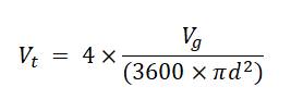
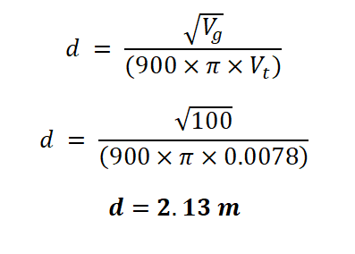
Where, Vg is gas volumetric flow (m3/hr) and 'd' is vessel diameter
Hence,
Considering the L/D ratio requirement,
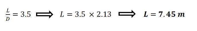
This length has to be checked to be compliant with project specification of liquid residence time between HLL and LLL.