Reverse temperature detectors (RTDs) are temperature sensors that include a resistor. The resistance value of this resistor metal is a strong function of the resistor metal temperature. Changes in metal temperature are reflected and noted as changes in electrical resistance. The reverse temperature detectors also include a few wires. The number of wires is either 2, 3 or 4.
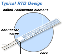
Reverse Temperature Detector (RTD) components
RTDs are generally characterized by the following aspects:
- Reverse temperature detectors offer a wide temperature measurement range (from approximately -200 degC to 850 degC), meaning that they can be used in all but the highest-temperature industrial processes.
- Accuracy of reverse temperature detectors is better than the accuracy of thermocouples.
- They have good corrosion resistance. For example, a reverse temperature detector made from a metal like platinum is not affected by corrosion or oxidation.
- These detectors are more fragile compared to thermocouples and therefore, precautions must be taken to protect it.
- Unlike the thermocouple, a reverse temperature detector is not self-powered. A current has to pass through the device in order to provide a voltage that can be measured.
- A reverse temperature detector is a more linear device than the thermocouple but it still requires curve-fitting.
RTDs are mostly made by platinum (Pt), since platinum has higher temperature withstanding capabilities and is more stable and repeatable compared to materials like nickel, copper and nickel-iron alloy.
Platinum Reverse Temperature Detectors
There are basically two standards in use nowadays for Platinum Reverse Temperature Detectors: the European standard and the American standard.
The European standard, IEC 751, is the most common one in use. It requires the RTD to have an electrical resistance of 100.00 Ohms at 0°C and a temperature coefficient of resistance (TCR) of 0.00385 between 0 and 100°C (the value of 0.00385 is actually the slope from 0 to 100 degC). That is the reason why the term 'PT100' is also used very often to describe RTDs.
There are generally two resistance tolerances specified in IEC7 51:
Class A = ±(0.15 + 0.002×t)°C and
Class B = ±(0.3 + 0.005×t)°C, t being the measured temperature
Industry-wide, the following resistance tolerances are used: ±1⁄3 × (Class B tolerance) and ±1⁄10 × (Class B tolerance).
The combination of resistance tolerance and temperature coefficient dictate the resistance vs. temperature characteristics for the sensor in question. The bigger the tolerance, the more the sensor will deviate from a generalized curve, resulting in more variation (interchangeability) from sensor to sensor. This is very important when a sensor needs to be replaced and a low interchangeability error is desired.
Number of wires
- The 2-wire construction is typically used only with high-resistance sensors, when lead lengths are short or when high measurement accuracy is not stipulated.
- Sensors using the 3-wire construction are perhaps the most common design. It is widely used in both industrial processes as well as various monitoring applications.
- Sensors using the 4-wire construction are mostly used when very precise measurements are needed, for example in laboratories. The fourth wire allows the meassuring equipment to factor out any unwanted resistance from the measurement circuit, thus reducing measurement error.
https://enggcyclopedia.com/2011/07/thermocouples/