What is Safeguarding Memorandum?
Safeguarding Memorandum (SM), as defined by Shell Oil, is a summary description of the final level of protection (safeguard) against uncontrolled loss of containment of hazardous materials in a process plant/facility. A Safeguarding Memorandum is the result of a study of the process design. The Safeguarding Memorandum shall be prepared from the Process Engineering Flow Scheme (PEFS) or P&ID, by Process Engineer. It is normally then incorporated into the Operating Manual of facility.
The details of the instrumented protective functions are described by the process control engineer in the Control and Safeguarding Narratives document.
Purpose of Safeguarding Memorandum
The objective of the Safeguarding Memorandum is to identify and summarize the protective devices which are installed as the final level of protection against uncontrolled loss of containment of toxic and/or flammable materials due to ruptures, failures of seals, gaskets, welds, etc. These devices are known as 'Ultimate Safeguards'.
The Safeguarding Memorandum also identifies the elements that when fully open or removed can lead to relief flows exceeding (e.g. 25%) of the design capacity of the particular relief device in the plant.
It further identifies and clarifies the interfaces with other units and utility systems.
A Safeguarding Memorandum document provides a useful safety training aid for operating personnel.
Typical contents of the Safeguarding Memorandum
A Safeguarding memorandum should include the following sections:
1. An Introduction to introduce the subject and specify any deviation of system
2. Final safeguards: summary of relief valves, rupture disks and instrumented protective functions
- Safety/relief valves summary datasheet
- Rupture disks and other relief devices: tag number, set pressure, service, location and governing case.
- Instrumented protective functions: tag number, location, protection function.
3. Description of individual relief cases
A description shall be given of what will happen in the following cases:
- Electrical power failure: Total power failure, single power failure, partial power failure
- Total cooling water failure
- Steam failure
- Total instrument air failure
- Inadvertent valve opening
- control valve failure
- Fire
- Other failure
4. Description of mitigation systems: Remotely Operated Valves (ROVs), ESD, emergency depressuring systems, water spray, deluge systems, etc
5. Description of instrumented protective functions
6. Interface with other units/systems:
A description of the interfaces with upstream/downstream units, and escalating effects that may arise and the adequate protection provided.
Typically the following interfaces would be described:
- Utilities systems;
- Flare system;
- Feed supply (feed surge drum/crude unit)
- Disposal system;
- Off-gas system
7. Miscellaneous
A section in the safeguarding memorandum document shall cover the safeguarding aspects that have not been addressed in the previous sections.
For example,
- Prevention from blockage of relief valve such as heat tracing/insulation, flare knockout drum, purging/flushing, rupture disks, etc.;
- Facilities for on-stream testing of safeguards;
- The interlocking system;
- Non-return valves, method of identifying these non-return valves in the field;
- Gas detection equipment (H2S, hydrocarbons, etc.)
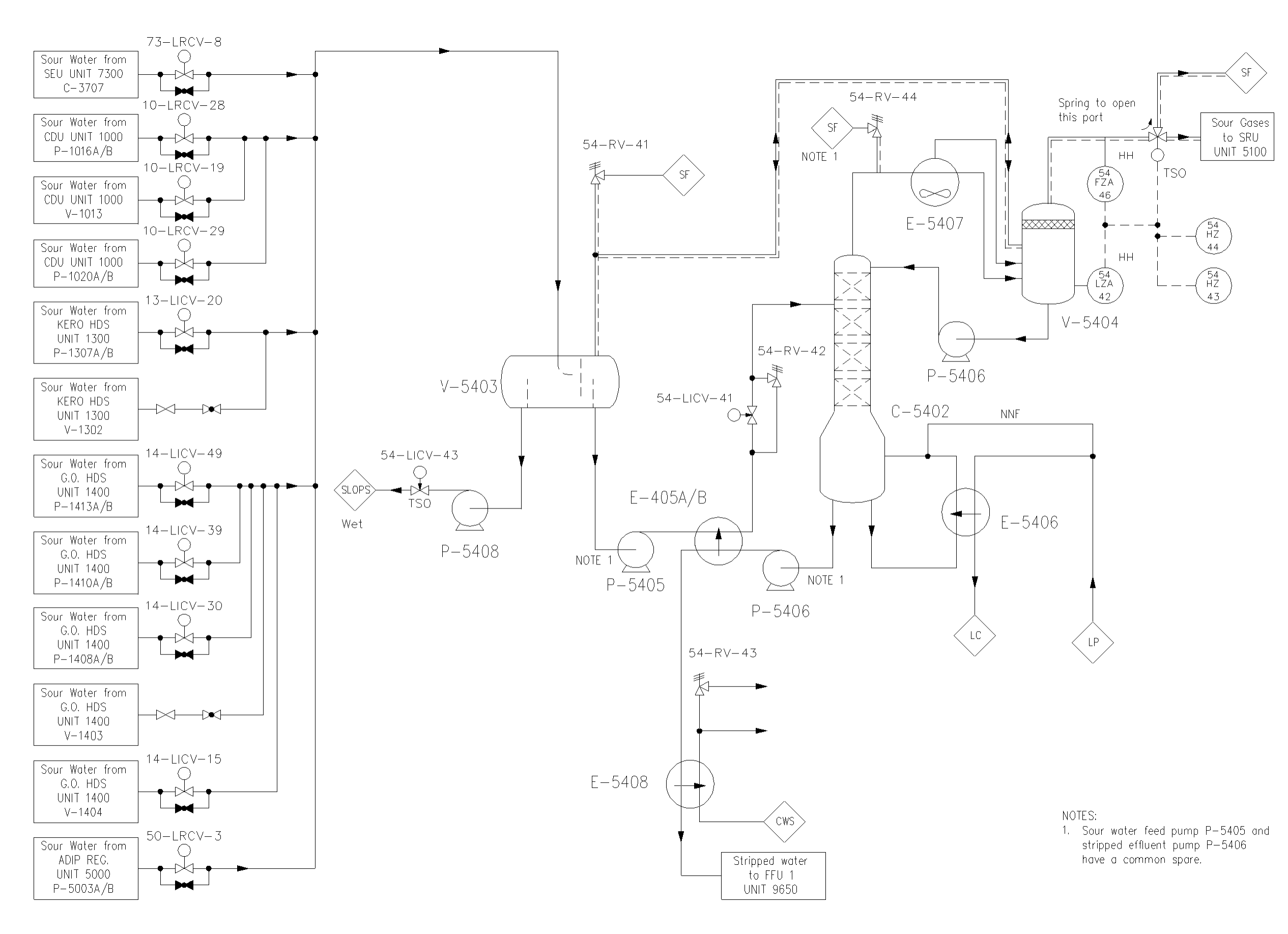
8. Process Safeguarding Flow Scheme (PSFS)
Process Safeguarding Flow Scheme is an integral part of the Safeguarding Memorandum, to highlight the most important safeguarding features.
A PSFS is as simplified version of a number of Process Engineering Flow Schemes (PEFS) (aka P&ID)
The PSFS should shows:
A) Final safeguards:
- Relief valves;
- Rupture disks;
- Thermal expansion valves; however, those for pumps and those in cooling water service may be omitted;
- Instrumented protective functions against loss of containment.
B) Capacity determining components:
- Trip valves, control and bypass valves, and restricting devices which, if inadvertently opened, can lead to relief flows in excess of 25 % of the design
- Capacity of the relief device.
- For each control valve shown, the PSFS shall indicate spring action, stay-put device, minimum stop, etc.
C) Mitigating systems
- Emergency shutdown valves, spring action;
- Remotely operated valves (ROVs) that are installed specifically for handling emergency situations.
D) The relevant interfaces with other units or systems, including the utilities and the flare and relief systems
An example of PSFS is given as below: