In a split range control loop, output of the controller is split and sent to two or more control valves. The splitter defines how each valve is sequenced as the controller output changes from 0 to 100%. In most split range applications, the controller adjusts the opening of one of the valves when its output is in the range of 0 to 50% and the other valve when its output is in the range of 50% to 100%.
The principle of a split range control is illustrated in the following example:
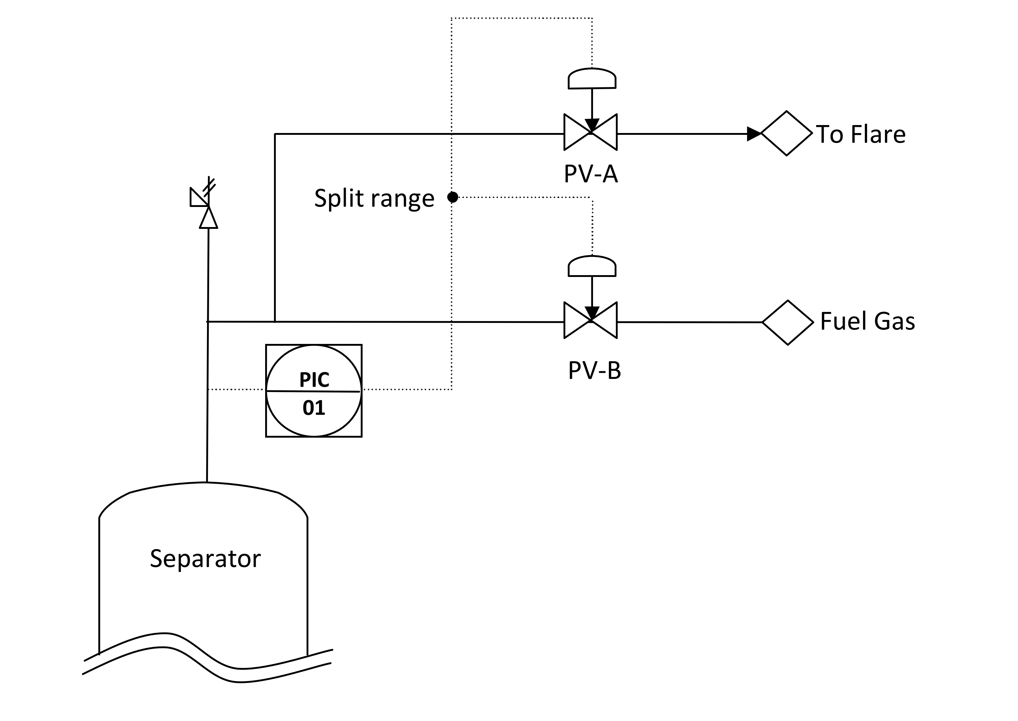
In figure1, PIC-01 controls the pressure of the separator for liquid-vapor hydrocarbons, by mean of a split range controller with the output signal split and sent to two pressure control valves PV-A and PV-B. When pressure increases, the fluid shall be discharged to flare. When the pressure decreases, Fuel gas is introduced to compensate the pressure of the separator
The fuel gas valve (PV-B) needs to close in response to increasing of pressure of the separator, while the flare valve (PV-A) will need to open when the pressure increases beyond setpoint.
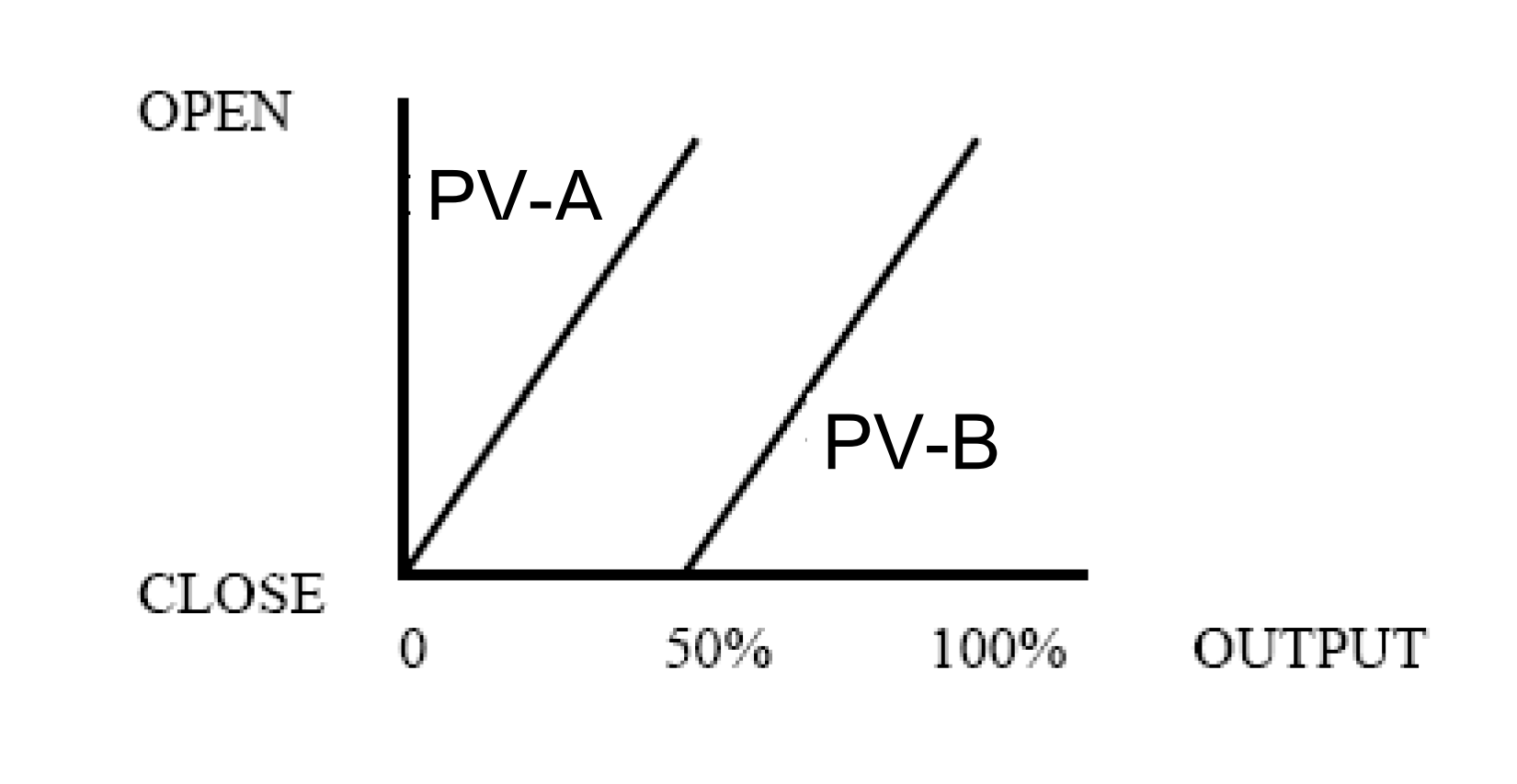
- When the pressure increases beyond setpoint in range of with 0-50% controller output, PV-B shall close from fully open to fully close.
- When the pressure increases beyond setpoint in range of with 50-100% controller output, PV-A shall open from fully close to fully open.
In summary, valve actions by PIC-01 is as follow:

In this case, the service of both control valves is different, with respect to use of fuel gas and flaring for pressure control. Another case of use of split range control loop is when one control valve cannot be suitably designed to cover the complete operating range of the controller. In that case, valve with a smaller Cv operated between 0-50% range and the other operates for 50-100% range. For example, a pressure controller for accumulator drum in overhead of a stabilizer column splits range to open 2 control valves. In the low range (0-50 % range in response to high pressure of the stabilizer), the off gas is routed to a gas plant downstream, in the high range (50-100% range in response to high high pressure of the stabilizer) the off gas goes to flare by opening of valve B. The control valve actions is as follow: