A valve is a mechanical device that is used to control the flow of fluid in a piping system. Valve P&ID symbols are a critical part of P&IDs, as they represent the various types of valves used to control the flow of fluids or gases.
Commonly used valve P&ID symbols (Piping and Instrumentation Diagram symbols) for manual valves. Note that they may differ slightly from one project to another.
Gate Valve

In this type of valve, the gate is lifted from the fluid flow path. This enables fluid to pass through the valve. It is generally used when a straight flow of fluid and minimum restriction is desired.
Normally Closed Gate Valve

A normally-closed gate valve relies on an external force to open. During usual operations, these valves remain closed by using a spring. The gate is held in place by the valve body. When a system experiences critical conditions, the valve will open to ensure safety.
Ball Valve

It generally consists of a hollow rotary ball. When a valve is open ball's hole will be in line with the fluid flow, allowing passage for the flow of fluid. And when the valve is closed, the ball's hole will be rotated to 90 degrees and will restrict the flow of fluid. These valves can withstand extreme pressure/temperature and high-volume flow and are generally used for high flow capacity. The circle represents a hollow ball in the P&ID symbol of the ball valve.
Normally Closed Ball Valve

The concept of a normally closed ball valve is similar to a normally closed gate valve. In a normally closed ball valve, the upstream seat is designed to seal against the ball in the closed position, preventing any fluid from flowing through the valve.
Globe Valve

Globe valve consists of a circle at center that shows movable plug, and a stationary seat enclosed in a spherical body. The black circle represents the globe-shaped body of the valve. The disk is attached to a stem that is operated by a handle or actuator to control the fluid flow. It is excellent to be used as a control valve due to its complex flow path. This valve is known for precise throttling and control.
Butterfly Valve

It consists of a circular disc or vane that is positioned in the center of the valve body. The disc is attached to a shaft that passes through the center of the valve body and is operated by a handle or actuator. In P&ID symbol diagonal line represents the disc and the circle at the center represents the shaft. It can be used for liquids/gases that can easily be displaced when the valve disc closes.
Check Valve

A check valve is a type of nonreturn valve. These valves rely on the flow of fluid to open or close. They are designed to ensure the fluid flow only in one direction, automatically preventing the backflow. The arrow in the check valve P&ID symbol represents the direction of fluid flow.
Plug Valve

It consists of a conically tapered plug that can be rotated inside the valve body to control the flow of fluid. Generally, Plug valves are used where on-off control of inflow is required. Also, it can be used for moderate flow throttling and flow diversion using multiport valves.
Needle Valve

Needle valve P&ID symbol consists inverted triangle that shows a tapered needle-shaped plunger to control the fluid flow. This plunger can be raised and lowered by using connected actuators. Needle valves are used as bleed valves or drain valves in the block and bleed assembly.
Self Draining Valve

As the name suggests these valves come with a drain port. It is designed to automatically drain the liquid from a pipeline when the valve is closed. The downward arrow represents the liquid draining from a valve.
Integrated Block and Bleed Valve

It is typically used in applications where it is necessary to isolate a section of pipeline or equipment for maintenance or repair, while also providing a means to safely drain or vent any trapped fluid. The purpose of the block and bleed valve system is to isolate or block the flow of fluid in the system so the fluid from upstream does not reach other components of the system that are downstream.
Auto Recirculation Valve

These valves are used to automatically control the flow and recirculation of fluids. The valve operates by sensing the fluid flow rate and automatically adjusting the valve to recirculate the fluid back to the pump or upstream piping when the flow rate is below a predetermined threshold.
Angle Valve

The angle valve has an angled inlet and outlet, which allows the valve to be installed at a right angle to the piping system. It can be used for pipes joining at an angle. Angled inlet and outlet can be seen in the angle valve p&id symbol schematic.
Angle Globe Valve

The angle globe valve is a variation of the standard pattern globe valve. It has an angled inlet and outlet in the glob-shaped body, which form a 90-degree angle to each other, unlike the straight alignment in the standard valve.
3-way Valve

A 3-way valve has three ports, one inlet, and two outlets. The valve allows fluid to flow through either the first outlet or the second outlet, depending on the position of the ball or plug.
Y Blowdown Valve

A Y blowdown valve is a type of valve that is commonly used in steam and water systems to remove sediment, dirt, and other impurities that accumulate in the system over time. The valve is designed with a "Y" shaped body and a valve disc that is connected to a stem.
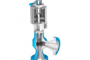
Angle Blowdown Valve

The angle blowdown valve is a type of valve that is installed at an angle to the piping system and features a needle-shaped trim located within a venturi diffuser. The venturi diffuser allows for sufficient area for high-velocity flashing water, which prevents a choked flow.
More references for creating P&IDs
- Typical P&ID arrangements and P&ID symbols for process design
- Basics of P&IDs (Piping & Instrumentation Diagram)
- P&ID software reviews
- Typical control valves P&ID arrangement