Piping support structures are used for supporting the weight of the pipes and fluids within them at regular distances. Pipe support spacing is maintained considering the total weight. Piping support structures must also be designed accounting for the thermal expansion / contraction, flow induced vibrations etc.
Design of the piping supports
The weight of piping running over long or medium distances in a process plant and related piping components must be supported to achieve five objectives:
- Minimize stresses in the piping
- Maintain the intended layout and slope
- Avoid excessive sag
- Minimize reaction loads on equipment nozzles
- Optimize the type, size and location of pipe supports.
Thumb rules for pipe support spacing
To achieve these objectives, and given the pipe routing, the design process starts by placing weight supports at regular intervals, following a support spacing guide such as given below in Table-1. These spacing values are based on ASME B31.1 standards.
This is a classic spacing table for steel pipe. It is based on a maximum bending stress of 2300 psi and maximum sag at mid-span of 0.10". In practice, longer spans are usually feasible, with a deadweight bending stress in the order of 5000 psi to 10,000 psi; provided the sag between supports remains acceptable.
As a rule of thumb, the spacing of pipe supports for steel pipes in liquid service, expressed in feet, may be taken as the nominal pipe size, expressed in inches, plus ten. For example, the spacing of pipe supports on a 6" line will be approximately 6 + 10 = 16 feet.
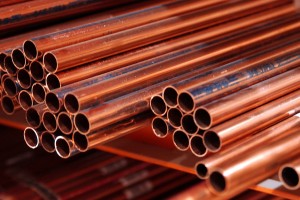
This spacing changes at high temperatures and for materials other than steel. For example, for copper tubing, support spacing varies from 8-ft for 1" tubing to 12-ft for 4". For PVC pipe the spacing depends on the pipe schedule and operating temperature. The span is 4-ft for %" pipe up to 6-ft for 4" schedule 40 pipe at ambient temperature; approximately 1-ft more for schedule 80, and half that spacing at 150°F. For fiber reinforced plastic pipe (FRP), support spacing in liquid service would vary from around 11-ft for 2" pipe to 22-ft for 8" pipe; and for gas service 17-ft for 2" to 40-ft for 8". For high density polyethylene (HDPE) the spacing would vary from 7-ft for 4" pipe with SDR (diameter over thickness) of 11.0, to 16-ft for 24" pipe.
In the simplest cases, the reactions, moments and deflections of pipe spans due to weight can be estimated using beam formulas. For example, in the cases illustrated in table-1, the reactions (R), moments (ME at end, MC at center and ML under load) and sag (d) of pipe spans are:
|
Support Spacing for Steel pipe (ASME B31.1) |
||
|
Pipe Size (in) |
Water (ft) |
Gas (ft) |
|
1 |
7 |
9 |
|
2 |
10 |
13 |
|
3 |
12 |
15 |
|
4 |
14 |
17 |
|
6 |
17 |
21 |
|
8 |
19 |
24 |
|
12 |
23 |
30 |
|
16 |
27 |
35 |
|
20 |
30 |
39 |
|
24 |
32 |
42 |