Process Instrument Datasheet
Process Instrument datasheets are developed to enable the Instrument engineers to prepare documentation required for inquiry and purchase of instruments. The process datasheet will be attached to and form part of the purchase order for the instruments. Instrument engineers are responsible for creating the instrument tag-numbers and entering the general information such as P&ID reference, line number, suppliers, package number etc. into the engineering database. The process data for those instruments is provided by process engineers.
Level Instrument Datasheet
The operating and design process conditions and measurement range for each process level component (level gauge, level transmitter, level switch etc.) are defined by the process engineers. Based on that the vendors can specify and size the instrument required. The fluids that the level instrument is in contact with shall be fully identified as they exist in the level instrument, and items such as the presence of solids, dissolved gas content, presence of corrosive or poisonous components should be identified. The physical properties of the fluids must be established in the process datasheet.
The process data is usually specified as single values, not a range. The process engineers shall select a value from a range for the vendor to use in his calculations.
General information in a level instrument datasheet
Tag Number: Instrument tag numbers are usually made up of a number of components which vary from project to project. One part of the tag number, usually letters, defines the type of instrument (e.g. 'LT' for level transmitter) whilst a numeric part defines the 'instrument loop number'. The instrument loop number is usually based on the unit number and a sequence number.
Service: A description of the duty such that the function of the instrument and its place in the process system can be understood.
P&ID No and Line/Equipment: This is the tag number of the vessel or tank the level is measured in.
Equipment Conditions: The main rule for these is that they should be consistent with the corresponding vessel/tank data sheet.
Design Temperature: The minimum and maximum design temperatures that is consistent with the corresponding vessel/tank datasheet.
Design Pressure: Design pressure to be entered consistent with the corresponding vessel/tank data sheet. Vacuum conditions should be included.
Corrosive Compounds: The following could be mentioned:
- saline produced water
- scale
- sand
- hydrogen sulphide (only if NACE materials are required)
- hydrogen (if hydrogen embrittlement is a problem)
- wet carbon dioxide
- Chlorine content (seawater service)
- Oxygenators such as methanol etc.
Fluid (upper/lower): A short description of the type of medium in the upper and lower layers, e.g., "seawater/air", "crude oil/hydrocarbon gas" etc.
Operating Conditions: The conditions those are consistent with the corresponding vessel/tank data sheet.
- Operating Temperature and pressure: The range of operating temperature and pressure to be entered consistent with the corresponding vessel/tank data sheet.
- Upper Fluid Density at temperature and pressure: This should be the density of the upper fluid in the level instrument consistent with the process data sheet for the corresponding vessel. This will generally be a gas density for liquid level measurement, and oil density for the interface measurement on a three-phase separator.
- Lower Fluid Density at T & P: This should be the density of the lower fluid in the level instrument consistent with the process data sheet for the corresponding vessel. This will generally be an oil density for liquid level measurement, and water density for the interface measurement on a three-phase separator. A range of densities may be given in a note.
Alternative Case: During a start-up/late in field life case a different upper/lower fluid density may occur, this must be noted.
Control Setting:
Level Settings relative to: is a reference point on the vessel or tank, which we refer level settings to.In general this should be "bottom tangent line" for vertical cylindrical vessels, and "vessel bottom" for horizontal drums or rectangular tanks. This reference and the level settings are used by the instrument engineer to position the level instrument on the tank.
Level Settings: There are two main items to be considered here - which level settings do we define, and how do we set the values.
The level settings are defined by process engineers on the P&ID, e.g. if a low level alarm function is shown on the P&ID, then a low level is denoted by the instrument engineers on the data sheet.
The normal level is used when the level is controlled (e.g. an oil separator) or when to define the required range of a level instrument when there is no other way of doing it, e.g. in a tank which has no alarm or shutdown levels, but just an operating range, or in a diesel day tank where the low alarm is the top of the tank but we wish to monitor level down to a lower level. If neither of these considerations applies, then normal level is leaved blank.
If there are requirements for level instruments to cover levels above/below alarm set points, the minimum range of instrument should be inserted.
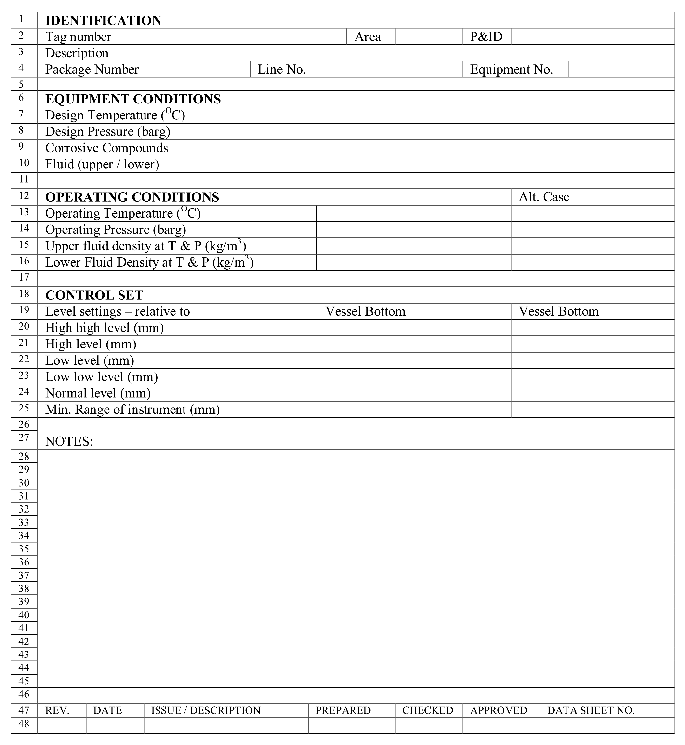
A typical process datasheet of Level instrument is given as below: