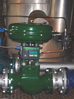
The Restriction Orifice is a plate that is used to restrict the flow and kill pressure downstream of the orifice. Process Instrument datasheets are developed to enable the instrumentation engineers to prepare documentation required for inquiry and purchase of instruments. The process datasheet will be attached to and form part of the purchase order.
Restriction orifice datasheet
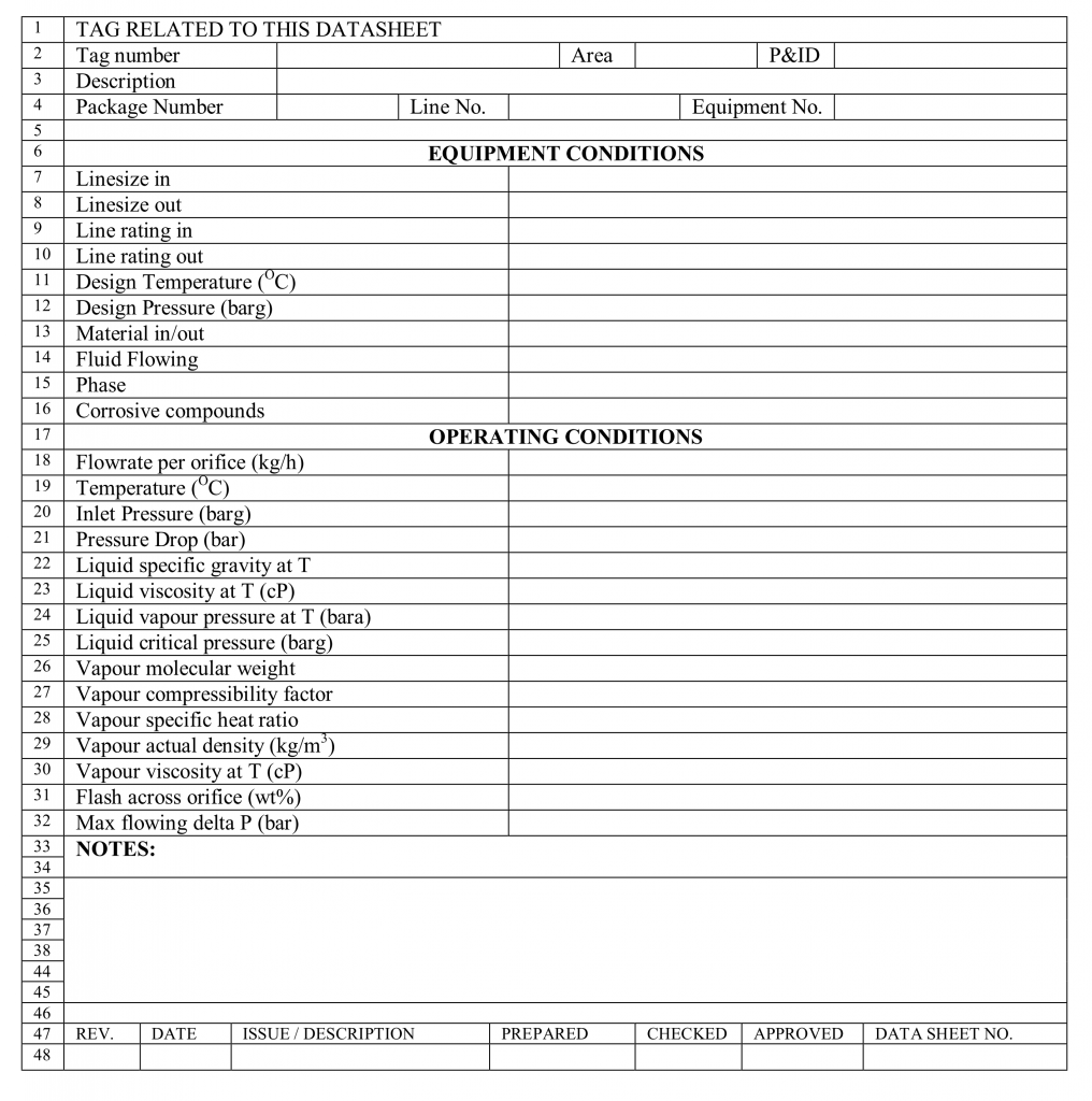
The contents included in a restriction orifice datasheet are as follows:
Identification
Tag No: Transferred from the P&ID system to the engineering database system.
Service: A description of the duty such that the function of the function of the flow element and its place in the process system can be understood.
Area: This entry is used to determine which fabrication yard the instrument is delivered to.
P&ID No and Line/Equipment: this entry is transferred from the P&ID system
Supplier and Model
Equipment Conditions
Line size: Inlet & outlet: These line sizes are the nominal upstream and downstream line sizes.
Line Rating: Inlet & outlet: This is the ANSI flange rating of the piping upstream and downstream of the flow element e.g. 300 lb (Imperial units) or PN50 (Metric jobs). This is the same both upstream and downstream.
Design Temperature/Pressure: Minimum and maximum design temperatures/pressure to be entered, consistent with line list information for the line.
Material in/out: Material in upstream/downstream piping of the orifice.
Fluid Flowing: A short description of the type of fluid e.g. "seawater", "crude oil" or "hydrocarbon gas".
For utility services, the "service code" description of the medium included in the piping line number can be used here.
Phase: This should be selected from one of the following depending of which best represents the service in the orifice:
- Liquid
- Flashing liquid
- Liquid and vapour
- Condensing vapour
- Vapour
Corrosive Compounds: the important information about the flowing fluid which should be aware of. The following should be mentioned:
- saline produced water (due to risk of SCC and scale laydown)
- scale
- sand
- hydrogen sulphide (only in NACE materials are required)
- hydrogen (if hydrogen embrittlement is a problem)
- wet carbon dioxide
- acid pickling (if line is part of a circuit which is to be pickled)
- oxygenators as MeOH, MEG and TE Flowrate per orifice:G
Operating Conditions
Flowrate: This flow defines the three sizing case for the flow orifice
Temperature: The inlet temperature to the orifice for the design flow case.
Inlet Pressure: The total pressure at the inlet to the flow element. This must be taken from the system hydraulic calculations, and must take account of static head and friction losses on the inlet to the orifice.
Pressure drop: The total pressure drop over the orifice taken from system hydraulic calculation (e.g. relief network calculations).
Specific Gravity at operating temperature: The ratio of the actual density of the liquid to the density reference of a reference substance at a specific condition (water at standard conditions » 1000kg/m3).
Liquid Viscosity at temperature: Generally taken from associated process equipment data sheets (heat exchangers, pumps, vessels). The liquid viscosity is of no real interest to the sizing provided the fluid flow is fully turbulent (i.e. almost all cases in offshore design except for highly viscous, waxy crudes). The important thing then is consistency with other documentation.
Vapour Pressure: This value is critical for any liquid which is near to equilibrium upon entering the orifice for the purpose of evaluating the potential for cavitation. The source is generally simulation of hydrocarbon liquids, or reference data for pure liquids (water etc.) and fuels.
Liquid Critical Pressure: The liquid critical pressure is used in orifice calculations for flashing as part of the routine to calculate the minimum pressure in the orifice. It can usually be contained from the process simulations for oil and gas streams, or from handbooks for water and other liquids.
Vapour Molecular Weight: Used for gas density determination, and obtained from flowsheets or process data sheets.
Vapour compressibility factor: This is the ratio of ideal gas density to actual gas density at operating conditions.
Vapour Specific Heat Ratio: Obtained from the correlation for hydrocarbon gases based upon reduced pressure and temperature and molecular weight. The reduced pressure and temperature of the process stream can be deduced from "Process" simulations, where critical values are given. Typical values for hydrocarbon are in the range of 1.25 to 1.35, 1.40 for air, and 1.41 for nitrogen. This value is used in the capacity calculation as an input to the "expansion factor" by the vendor, and is an integral part of all expanding gas fluid flow situations.
Vapour Actual Density: This is the gas density at operating conditions, used by instrumentation engineers in their calculations.
Vapour Viscosity at temperature: This is the gas viscosity at operating conditions, generally taken from process simulations or from associated process equipment data sheets (e.g. heat exchangers, pumps, vessels).
Flash across orifice: This is the increase in vapour fraction across the orifice. If no vapour is defined at the inlet, or the flash is greater than around 10%, the outlet vapour properties should be included as a note. If the flash is negative (i.e. retrograde condensation) then the negative value should be confirmed and explained as a note
Maximum flowing pressure drop: This is important to calculate correct thickness of the orifice plate.
A typical process datasheet for Restriction Orifice is given as follow:
