Line sizing calculations are used in the design of piping systems to determine the optimal diameter of the pipes to ensure that the fluid flows through the system with the desired flow rate and pressure drop. Proper line sizing is important to avoid problems such as excessive pressure drop, inadequate flow rates, and excessive energy consumption.
The line sizing calculations take into account various factors, including the fluid properties (density, viscosity, and specific heat), the flow rate, the desired pressure drop, and the length of the pipeline.
Table of content:
Line sizing
Line sizing calculations
Line sizing
Line sizing is the process of selecting the appropriate diameter for a pipeline or duct based on the flow rate, fluid properties, and other factors. The goal of line sizing is to ensure that the pipeline can handle the required flow rate with minimal pressure drop and energy consumption.
The factors that affect line sizing include the type of fluid or gas being transported, the flow rate, the pressure and temperature of the fluid, and the length and layout of the pipeline or duct. Additionally, the frictional losses that occur due to the roughness of the pipeline walls and the fluid viscosity must also be considered.
The first step in line sizing is to determine the flow rate of the fluid or gas that will be transported through the pipeline. The flow rate is a critical parameter in line sizing because it determines the required diameter of the pipeline.
The next step is to select a pipeline diameter that can handle the required flow rate while minimizing pressure drop. Pressure drop is the reduction in pressure that occurs as fluid flows through a pipeline due to frictional losses. The pressure drop is proportional to the square of the flow rate and inversely proportional to the diameter of the pipeline. Therefore, increasing the diameter of the pipeline can reduce the pressure drop and improve efficiency.
These calculations ensure that the selected pipeline diameter will provide the required flow rate with a minimal pressure drop.
Line sizing calculations
Problem Statement:
Calculate the size of the line to handle 100,000 kg/hr of water. The approximate length of this line is around 200m. This water stream is available at 5 barg pressure and 300C.
The project standards requirements are - fluid velocity < 3 m/s and pressure drop < 4.5 bar/km
Consider 20 nos. of 900 elbows and 4 gate valves in the line and estimate total pressure drop.
Solution:
This sample problem is solved in following 3 steps.
Step 1.
Solving this sample problem requires determination of important physical properties of given fluid (water) at given temperature and pressure conditions.
Using EnggCyclopedia's Liquid Density Calculator, water density at 300C =993.41 kg/m3
Using EnggCyclopedia's Liquid Viscosity Calculator, water viscosity at 300C =0.81 cP
Step 2.
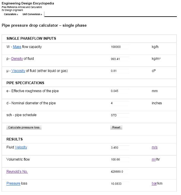
Use EnggCyclopedia's Pipe pressure drop calculator for single phase flow to get the pressure drop in bar/km. Different pipe sizes are tried and the results are reported in following images.
4" line size.
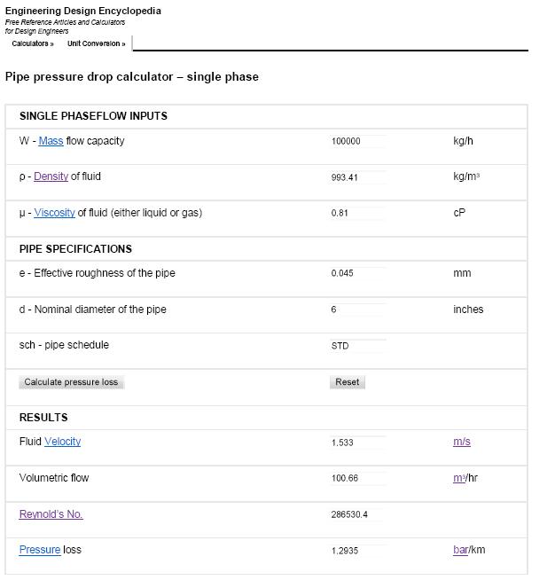 The 4" line size does not satisfy limitations on fluid velocity and pressure drop / km (velocity<3 m/s and pressure drop<4.5 bar/km). The next higher size of 6" is in accordance with these limitations and hence chosen as the line size.
Step 3.
Final step of solving this line sizing problem is to calculate total pressure drop for this line size considering the fittings and bends in line. EnggCyclopedia's K factor calculator can be used for this purpose.
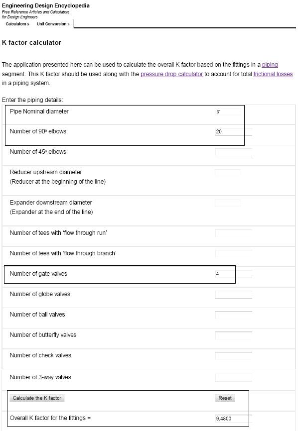 Contribution of fittings (K factor) to the total pressure drop = KρV2/2
= 9.5 X 993.4 X 1.532/(2 X 105) bar = 0.11 bar.
Pressure drop due to straight pipe length (200 m) = 1.3 bar/km X 0.2 km = 0.26 bar.
Total pressure drop = 0.26 + 0.11 = 0.37 bar
