Centrifugal compressors are an important type of compressor used in various industrial applications. They work by converting the kinetic energy of a rotating impeller into potential energy of the compressed gas.
In the industries, centrifugal compressors are commonly used in air conditioning and refrigeration systems, gas turbines, and the petrochemical industry. They offer high efficiency and reliability, as well as a wide range of flow rates and pressure ratios.
The purpose of this blog post is to provide an overview of centrifugal compressors, including how they work, their applications, advantages and disadvantages.
Table of Content:
1. What is Centrifugal Compressor?
2. How Does a Centrifugal Compressor Work?
3. Parts of Centrifugal Compressor
4. Centrifugal vs Axial Compressor
5. Centrifugal Compressor Surge
6. Centrifugal Compressor Choke
7. Centrifugal Compressor Maps
8. Typical PFD for centrifugal compressor systems
9. Typical P&ID arrangement for centrifugal compressor systems
What is Centrifugal Compressor?
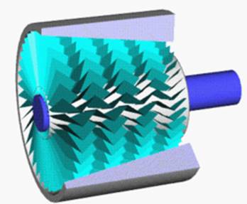
Centrifugal compressors are a type of dynamic compressor that uses a rotating impeller to increase the pressure of a gas or fluid. The gas or fluid enters the compressor through the inlet and is directed into the rotating impeller. The impeller blades then accelerate the gas or fluid outward, increasing its velocity and kinetic energy. This high-speed gas or fluid then enters the diffuser, which converts the kinetic energy into pressure energy, resulting in a higher pressure.
How Does a Centrifugal Compressor Work?
Centrifugal compressors consist of several basic components, including an impeller, a casing, and inlet and discharge ducts.
The impeller is a rotating disk with curved blades that spin rapidly inside the stationary casing. As the impeller rotates, gas is drawn into the center of the impeller through the inlet duct. The blades on the impeller impart kinetic energy to the gas, causing it to move radially outward and increase in velocity.
The high-speed gas is then directed into the stationary casing, where it undergoes a change in direction and velocity. This causes a pressure rise and a decrease in volume. The compressed gas is then discharged through the discharge duct.
Parts of Centrifugal Compressor
Centrifugal compressors consist of several key parts that work together to compress gas or air.
- Impeller: The impeller is a rotating component that consists of curved blades that compress gas or air as it rotates. The impeller is the most critical part of the compressor and is responsible for the compression process.
- Diffuser: The diffuser is a stationary component that is located downstream from the impeller. Its primary function is to convert the high-velocity, low-pressure gas or air coming from the impeller into high-pressure, low-velocity gas or air. The diffuser usually consists of stationary vanes or passages that guide the gas or air and slow it down.
- Volute or Scroll: The volute or scroll is a stationary component that collects the high-pressure gas or air from the diffuser and directs it to the discharge nozzle. The volute or scroll usually has a spiral shape that helps to reduce turbulence and improve efficiency.
- Shaft: The shaft is a rotating component that connects the impeller to the driver, such as an electric motor or a gas turbine. The shaft is usually supported by bearings that allow it to rotate smoothly.
- Bearings: The bearings are components that support the shaft and allow it to rotate smoothly. The bearings may be either oil-lubricated or oil-free.
- Drive Mechanism: The drive mechanism is the component that drives the impeller. It may be an electric motor, a gas turbine, or some other type of driver.
- Casing: The casing is the outer shell of the centrifugal compressor that encloses all the other components. The casing usually consists of two halves that are bolted together.
- Inlet and Outlet Nozzles: The inlet nozzle is the component that allows gas or air to enter the compressor, while the outlet nozzle is the component that allows compressed gas or air to exit the compressor.
These are the main parts of a centrifugal compressor. The specific design and arrangement of these components can vary depending on the application and the manufacturer of the centrifugal compressor.
Centrifugal vs Axial Compressor
Axial and centrifugal compressors typically fall into the category of rotodynamic compressors. Check this post to compare centrifugal vs axial compressors, understand the difference between them and look at different uses cases.
Centrifugal Compressor Surge
Centrifugal compressor surge is seen as a very dangerous and detrimental phenomenon in compressed air systems, dangerous because it causes the compressor to vibrate and detrimental because it causes damage to the compressor parts. Compressor surge only occurs in dynamic compressors (Axial and Centrifugal) due to their nature. To understand compressor surge check given post.
Centrifugal Compressor Choke
Compressor choke is an abnormal operating condition for centrifugal compressor. Choking of centrifugal compressor occurs when the compressor is operating at low discharge pressure and very high flowrates. These high flowrates at compressor choke point are actually the maximum that the compressor can push through. Any further decrease in the outlet resistance will not lead to increase in compressor output.
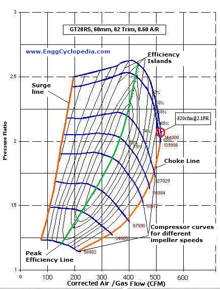
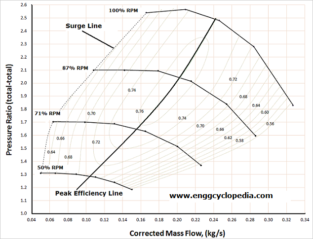
Centrifugal Compressor Maps
Compressor maps are developed by the manufacturer of dynamic compressors. They are compressor equivalents of the pump performance curves. It is the performance chart of a specific compressor which manufacturer calculates and draws up for the unique design characteristics of that compressor.
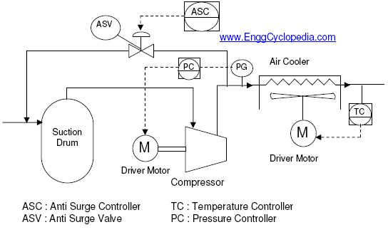
Typical PFD for centrifugal compressor systems
This post contains typical process flow diagram for centrifugal compressor system. Common equipment included in such systems are compressors, driver motors or turbines, suction knock out drums (KOD) to remove traces of liquid from the gas going into the centrifugal compressor and aftercoolers which help lower the temperature of the discharge gas from compressor.
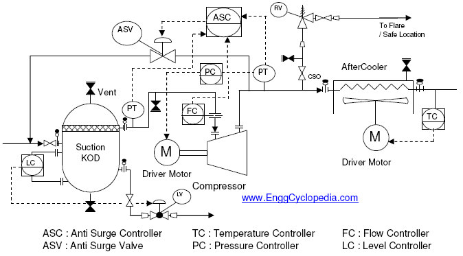
Typical P&ID arranement for centrifugal compressor systems
Typical P&ID arrangement for centrifugal compressors is shown in this post including the requirements for isolating, draining/venting and bypassing the compressors used in a process plant. Requirements for flow, temperature and pressure monitoring is also indicated along with requirement of emergency anti-surge valves, driver motor/turbine, knock out drum, aftercoolers etc.