Control valve actuator P&ID symbols are very important because they allow engineers and technicians to quickly and easily identify the type of actuator used in a particular application. This, in turn, helps them to understand the operational characteristics and requirements of the actuator, and to troubleshoot any issues that may arise. Control valve actuators regulate the flow of fluids.
Table of content:
Control valve assembly
Control valve actuators P&ID symbols
Control valve assembly
These are critical components in many industrial and commercial processes that require accurate control of fluid flow. A control valve assembly is a group of components designed to manage the flow of gas or liquid through a pipeline or process system. It includes a valve body, actuator, positioner, and associated parts such as solenoid valves, limit switches, and pressure regulators.
The valve body is the primary component and it regulates the flow of fluid through the pipeline. It can be of various types such as globe, butterfly, or ball valves, depending on the application. The actuator moves the valve disc or plug to control the flow, and it can be powered by electricity, pneumatic or hydraulic pressure, or manually.

This is a general P&ID symbol to understand the control valve assembly and actuator.
Control valve actuator P&ID symbols
There are several different P&ID symbols used to represent different types of control valve actuators. Here we have discussed commonly used P&ID symbols for control valve actuators.
Note that they may differ slightly from one project to another.
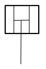
Manual (handwheel)

A manual handwheel actuator is operated manually by turning a handwheel. The handwheel actuator typically consists of a handwheel that is connected to the valve stem through a set of gears or a chain. The horizontal line shows the handwheel and the vertical line shows the stem in the given P&ID symbol.
Balanced diaphragm actuator

A balanced diaphragm actuator uses two diaphragms to move the valve stem and control the flow of fluids. The actuator connects the valve stem between the two diaphragms, which are balanced against each other to provide equal forces on both sides. The balanced diaphragm actuator applies pressure to one of the diaphragms, which moves the valve stem in one direction. The movement of the valve stem controls the position of the valve plug, allowing the actuator to regulate the flow of fluid.
Motor actuator

A motor actuator uses an electric motor to move the valve stem and control the flow of fluids. The P&ID symbol for a motor actuator typically consists of a circle that has an "M" inside to indicate that the actuator is motorized.
Spring actuator

To move the valve stem and control the flow of fluid this type of actuator uses a spring. The spring is pre-loaded to a specific force, and when the actuator is pressurized, the spring force is overcome, and the valve is moved to a new position. When the pressure is released, the spring returns the valve to its original position. In the P&ID symbol of the spring actuator, inclined lines are drawn to represent the spring on the vertical line of the stem.
Pilot actuator

These actuators use a smaller control valve, called a pilot valve, to move the main valve to a new position, or to hold it in a set position. The pilot actuator is commonly used in applications where the valve is located in a hazardous or hard-to-reach area. It can be located near the main valve or in a remote location and can be operated manually or automatically.
Solenoid actuator

A solenoid actuator is a type of electromechanical device used to control the position of a valve. It uses an electromagnetic field to move a plunger or other mechanical element, which in turn can be used to actuate the valve.
Solenoid actuator with manual reset

It works in the same way as a standard solenoid actuator, but it can be manually reset after a power or control system failure.
1 Acting cylinder actuator

It is a type of mechanical device used to convert fluid pressure into linear motion. It typically consists of a piston or plunger, a cylinder, and a set of valves that control the flow of fluid into and out of the cylinder.
In this type of actuator, fluid pressure is used to move the piston or plunger in a single direction. Hence it is called "single acting." The direction of movement is determined by the position of the valves. This allows fluid to enter the cylinder on one side of the piston and exit on the other side and causing the piston to move in one direction.
2 Acting cylinder actuator

In a double-acting cylinder actuator, fluid pressure is used to move the piston or plunger in both directions. In this type, when the fluid is introduced into the other side of the cylinder, it pushes the piston in the opposite direction. This allows to perform work in the opposite direction.
Pilot-operated cylinder actuator

In a pilot-operated cylinder actuator, a pilot valve controls the fluid pressure. This eventually results in regulating the flow of fluid into and out of the cylinder. This type of actuator is similar to a double-acting cylinder actuator.
Pneumatic (Rotary) actuator
Pneumatic (rotary) actuators typically consist of a piston or vane that is mounted inside a cylinder. When compressed air is introduced into the cylinder, it creates pressure that causes the piston or vane to rotate, which in turn rotates the valve that is attached to the actuator.
Digital actuator

A digital actuator uses electronic signals to control the movement of a mechanical device, such as a valve or damper. These actuators are typically controlled by a microprocessor or other electronic controller that receives signals from a central control system.
Weight actuator

It uses the force of gravity to control the valve position. It consists of weight that is attached to a lever arm and eventually to a valve stem. When the weight is in a vertical position, the valve is closed. As the weight is tilted or moved to a different position, the stem moves, and the valve opens or closes.
Key actuator

To control the position of the valve this mechanical actuator uses a key. The key is inserted into a keyway or slot in the actuator, which is in turn connected to a valve stem. The valve can be opened or closed by turning the key.
Electro-hydraulic actuator

The electro-hydraulic actuator combines the precision of electrical control with the power of hydraulic pressure. This type of actuator uses an electric motor to drive a hydraulic pump, which generates fluid pressure to move a piston or actuator rod. The hydraulic pressure provides the force to move the actuator, while the electrical control system provides precise positioning and control.
Check this post to study typical control valves P&ID arrangement.