Control valve actuators are an integral part of control valves and help in regulating the fluid flow efficiently. Actuators convert various signals such as pneumatic, hydraulic, or electric signals into mechanical motion. This mechanical motion changes valve position and helps in the regulation of fluid flow.
Engineers need to understand the structure, working mechanism and types of valve actuators to select the proper actuator for specific applications. In this post, we will explore the structure, working and types of actuators.
Table of content:
1. What are control valve actuators?
2. How do valve actuators work?
3. Parts of valve actuators
4. Types of valve actuators
5. Self actuated pressure control valves
6. Valve actuator P&ID symbols
7. Pneumatically actuated valve datasheet
What are control valve actuators?
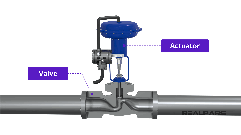
Control valves are one of the most important components in various process industries, as these valves are used to control different process parameters such as pressure, temperature, fluid flow, and level. Control valves control these parameters by adjusting valve position. Adjusting valve position increases or decreases valve opening, resulting in increased or decreased area for fluid flow. All process parameters can be maintained within the desired range or close to the set point by regulating the fluid flow.
However, control valves can not operate on their own and cannot change valve position. Control valve actuators are used for this purpose. Control valve actuators provide the necessary force and motion to the valve mechanism for changing the valve position.
Valve actuators receive control signals and convert them to mechanical motion according to requirements. This mechanical motion is passed to the valve using an actuator stem and valve stem. Eventually, the valve opens or closes depending on whether the flow rate needs to be increased or decreased.
How do valve actuators work?
The working mechanism of control valve actuators include conversion of input signals into mechanical force and motion to operate the valve. The detailed working is explained in this section.
- The actuator receives an input signal from the controller. According to the signal received power source is provided. The power source can be pneumatic, hydraulic or electric or may be in other form depending on the type of actuator.
- Pneumatic actuators use compressed air, hydraulic actuators use pressurized hydraulic fluid and electric actuators use electric power as their power source.
- The power source generates the force and moves the actuator mechanism.
- The actuator consists of several components such as diaphragm, gear, piston and yoke that converts force into linear or rotary motion.
- The actuator is connected to the valve by actuator stem and valve stem. When the actuator moves the motion will be transferred to the valve causing it to change the valve position.
- When the flow rate needs to be increased, the valve will be gradually opened. When the flow rate needs to be decreased, the valve will be gradually closed.
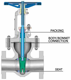
Parts of valve actuators
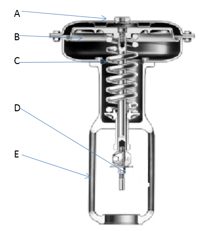
The actuator consists of various components, including the loading pressure connection, diaphragm, actuator spring, actuator stem, and yoke. The loading pressure connection determines how the pneumatic medium flows to control the valve's resting position. The diaphragm moves based on the pressure supplied, guiding the valve's opening.
The actuator spring ensures the valve remains closed or open in case of pneumatic supply failure. The actuator stem connects the actuator to the valve stem, transmitting motion to regulate fluid flow. The yoke provides mounting, connection, and clearance for the actuator stem within the valve body. Check the given post to explore detail of these parts.
Types of valve actuators
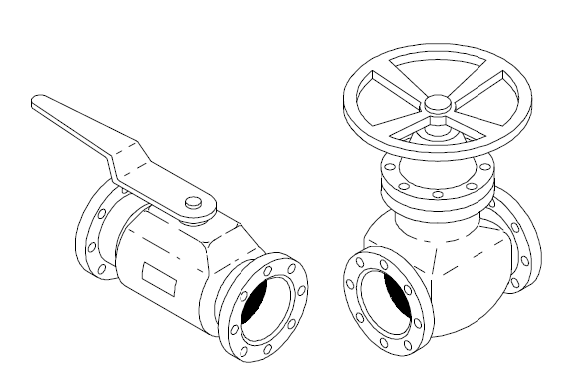
There are different types of valve actuators used for different applications. Control valve actuators can be classified into linear and rotary actuators based on motion, and into manual, electric, pneumatic, solenoid, hydraulic, and self-actuated actuators based on energy source. Manual actuators require manual operation, while other types enable automatic or semi-automatic valve operation. Check this post to explore details of these types of actuators.
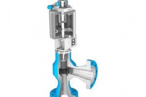
Self actuated pressure control valves
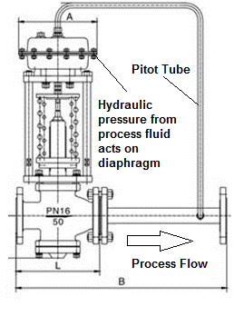
Self-actuated pressure control valves are devices designed to regulate pressure within a system without the need for external power or control signals. It operates based on the principle of utilizing the process fluid's energy to open or close the valve. This self-actuation mechanism simplifies the control system, reducing the complexity and costs associated with external power sources or control instruments. The given post explores self actuated pressure control valves thoroughly.
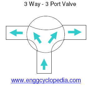
Valve actuator P&ID symbols
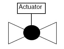
Control valve actuator P&ID symbols are very important because they allow engineers and technicians to quickly and easily identify the type of actuator used in a particular application. This, in turn, helps them to understand the operational characteristics and requirements of the actuator, and to troubleshoot any issues that may arise. Check this post to explore P&ID symbols of different types of actuators.
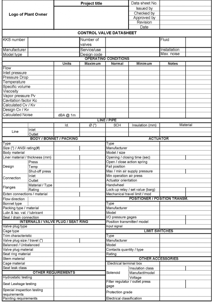
Pneumatically actuated valve datasheet
This post contains an illustration of a typical pneumatic-type control valve datasheet.