Venting systems are essential to protect tanks and vessels from overpressure and vacuum conditions that can occur during filling, emptying, or temperature changes. Inbreathing valves are a crucial component of the venting system, allowing air to enter the tank as the volume of liquid inside decreases. However, designing an effective inbreathing valve requires accurate venting calculations to ensure that it can provide adequate protection against vacuum conditions. In this post, we will explore the basics of venting calculation for inbreathing valves.
Table of content:
Pressure relief vacuum valve
Inbreathing valve
Venting calculation for inbreathing
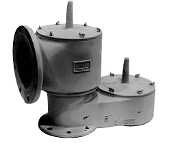
Pressure vacuum relief valve
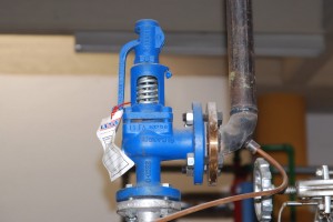
A Pressure Vacuum Relief Valve (PVRV) is a safety device commonly used in the oil and gas industry and other process industries to protect storage tanks, pipelines, and vessels from excessive pressure or vacuum conditions.
The valve is designed to automatically open when the pressure or vacuum inside the vessel reaches a set limit, thereby preventing potential damage or rupture that may occur due to overpressure or vacuum. The valve's opening allows gases or vapors to escape to the atmosphere until the pressure or vacuum condition returns to normal.
PVRVs can be of various types, including spring-loaded, weight-loaded, or pilot-operated. Spring-loaded PVRVs use a spring mechanism to control the opening and closing of the valve. Weight-loaded PVRVs use the weight of a counterbalance to control the valve, while pilot-operated PVRVs use a small pilot valve to control the main valve.
Inbreathing valve
An inbreathing valve is a type of pressure relief valve that allows air to enter a storage tank or vessel as the volume of liquid inside the tank decreases due to use or evaporation.
As the liquid inside the tank is removed, the pressure inside the tank decreases, which can cause a vacuum condition. If left unchecked, this vacuum condition can cause the tank to collapse or implode. An inbreathing valve allows air to enter the tank to equalize the pressure and prevent a vacuum condition.
Inbreathing valves are typically installed on the top of tanks or vessels and consist of a valve and a pressure relief device. The valve allows air to enter the tank as the pressure inside the tank decreases, while the pressure relief valve is designed to open automatically if the pressure inside the tank exceeds a certain level.
Venting calculation for inbreathing
Process tanks and vessels operating at low or atmospheric pressures are designed to handle low pressures and large variation in pressure can lead to damaging these equipments. Hence it is desirable to maintain these equipments at near atmospheric pressure (1.013 bara). This is done by providing a venting arrangement for inbreathing and outbreathing of air to protect against vacuum and overpressure respectively. The following information in this article pertains to protection of the low or atmospheric pressure storage tanks or vessels against vacuum, by inbreathing of air.
In process vessels and in storage tanks containing gas and liquid, sometimes vacuum can be created due to couple of possible reasons.
(i) Liquid movement out of the vessel or tank
(ii) Thermal Shrinking of the fluids in vessel or tank. In either case the vacuum can damage the structure of the tank and needs to be protected against.
An open vent or a pressure vacuum relief valve (PVRV) can be used to serve this purpose. These devices will allow air ingress to prevent vacuum build up in the tank. The minimum required venting flow for the inbreathing can be calculated using guidelines from API 2000. Different possible scenarios with the corresponding sample venting calculations are discussed in the following sections. Total outbreathing flow is finally calculated as the sum of outbreathing flow requirements due to liquid inflow and due to thermal expansion and evaporation.
Venting Calculation for Inbreathing due to liquid movement out of the tank
As per API 2000, the inbreathing flow should be sized to correspond to the maximum liquid movement out of the tank. The air ingress requirement is 5.6 SCFH (Standard ft3/h) of air for each 42 US gallon barrel or 0.94 Nm3/h of air for each m3/hr of maximum liquid emptying rate out of the tank, at any flash point.
Venting Calculation for Inbreathing due to thermal shrinking of fluids
The venting requirements for inbreathing vary corresponding to the total tank capacity. For large capacity tanks the venting inbreathing requirements are directly proportional to the combined shell and roof area of the tank which is responsible for heat transfer out of the tank leading to thermal shrinking of the vapor contents. For tanks with capacity in excess of 20,000 barrels, the venting requirements are roughly 2 SCFH per ft2 of total shell and roof area. For smaller capacity tanks, the inbreathing flow requirement for venting is 1 SCFH of air per barrel of tank capacity, as per API 2000.
Total outbreathing flow is finally calculated as the sum of outbreathing flow requirements due to liquid inflow and due to thermal expansion and evaporation.
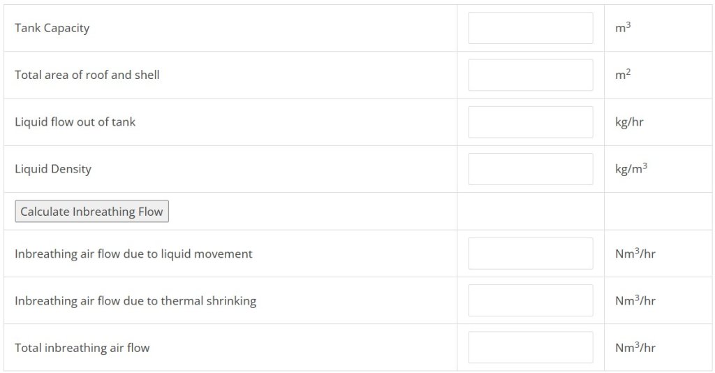
Normal Venting Calculator – Inbreathing Flow
Check Enggyclopedia's venting calculator for inbreathing flow.
