Heat exchanger area refers to the total surface area available for heat transfer between the hot and cold fluids in a heat exchanger. The heat exchanger area is a measure of the size of the heat exchanger and its capacity for heat transfer.
The purpose of discussing the heat exchanger area is to provide insight and understanding into the key aspect of heat transfer design and performance. The area of a heat exchanger plays a critical role in determining the efficiency and effectiveness of heat transfer in a heat exchanger. This post contains how to calculate the area of heat exchanger.
Table of content:
Problem statement
Step-1: Determine heat duty
Step-2: Determine the cold fluid outlet temperature
Step-3: Calculate the log mean temperature difference (LMTD)
Step-4: Calculate heat exchanger area
Importance of heat exchanger area
Problem statement:
An exchanger is used to cool hot oil (specific heat = 0.5 Btu/lb.°F) from 600°F to 400°F by using cold fluid which is at 100°F. The hot fluid flow rate is 10000 lb/hour, and the cold fluid flow rate is 75000 lb/hour. An initial estimate of the overall heat transfer coefficient (U) is 25 Btu/hr.ft².°F. Estimate the area of heat exchanger needed to cool hot fluid for the following 3 types of heat configuration.
- Co-current double pipe heat exchanger
- Counter-current double pipe heat exchanger
- 1,2 Shell and tube heat exchanger
Solution:
mH = 10000 lb/hour , mC = 75000 lb/hour
TiH = 400°F , ToH = 400°F, TiC = 100°F
U = 25 Btu/hr.ft².°F
CpH = CpC = Cp = 0.5 Btu/lb.°F
Step-1: Determine heat duty
The first step is to calculate the heat duty required to cool the hot oil by using energy balance calculation.
Q = mH × CpH × (ToH - TiH)
Q = (10000 lb/hour) × (0.5 Btu/lb.°F) × (400°F - 600°F) = -1 x 10⁷ BTU/hour
Step-2: Determine the cold fluid outlet temperature
From the energy balance calculation, we know that the heat absorbed by the hot fluid is equal to the heat removed by the hot fluid. So, by using the energy (heat) balance equation we can calculate the cold fluid outlet temperature.
mH × CpH × (TiH - ToH) = mC × CpC × (ToC - TiC) .........(Heat balance equation)
-1 x 10⁷ BTU/hour = (75000 lb/hour) × (0.5 Btu/lb.°F) × (ToC - 100°F)
ToC = 367°F
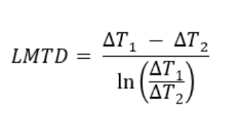
Step-3: Calculate the log mean temperature difference (LMTD)
LMTD can be calculated by using the LMTD equation for all three configurations.
(i) For counter-current heat exchanger:
ΔT1 = ToH - TiC = 400 - 100 = 300°F (At one end cold fluid enters and hot fluid exits.)
ΔT2 = TiH - ToC = 600 - 367 = 233°F (At the other end hot fluid enters and cold fluid exits.)
by definition given above, LMTD for counter current flow = (300-233) / ln(300/233) = 265°F.
(ii) For co-current heat exchanger:
ΔT1 = ToH - ToC = 400 - 367 = 33°F (At one end hot and cold fluids exit the heat exchanger.)
ΔT2 = TiH - TiC = 600 - 100 = 500°F (At the other end hot and cold fluids enter the heat exchanger.)
by definition given above, LMTD for counter current flow = (33-500) / ln(33/500) = 172°F.
Both These calculations can be verified quickly in EnggCyclopedia's LMTD calculator.
(iii) For 1-2 shell and tube heat exchangers:
The LMTD is valid only for heat exchangers with one shell pass and one tube pass. For a multiple number of shell and tube passes the flow pattern in a heat exchanger is neither purely co-current nor purely counter-current. In 1-2 shell and tube heat exchanger flow direction of two streams is a combination of counter-current and co-current flow. Hence to account for geometric irregularity, the Logarithmic Mean Temperature Difference (LMTD) has to be multiplied by a Mean Temperature Difference (MTD) correction factor to obtain the Corrected Mean Temperature Difference (Corrected MTD).
Correction factor (FT) is a function of R and S values and it can be determined from this chart. R and S are a function of inlet and outlet temperature and can be calculated as given below.
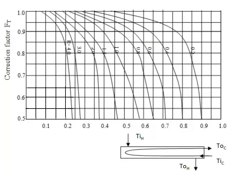
R = (TiH - ToH) / (ToC - TiC)
∴ R = (600 - 400) / (367 - 100) = 0.75
S = (ToC - TiC) / (TiH - TiC)
∴ S = (367 - 100) / (600 - 100) = 0.53
From the chart, we can determine Correction factor (FT) as 0.86 for an R value of 0.75 and an S value of 0.53.
To understand LMTD calculation thoroughly, check this post.
This is Enggcyclopedia's simple calculator to quickly calculate a correction factor.
Step-4: Calculate heat exchanger area
Calculate the area of a heat exchanger using the overall heat transfer equation.
The overall heat transfer rate (Q) is defined as - Q = U×A× LMTD ⇒ A = Q / ( U × LMTD )
(i) For counter-current heat exchanger,
A = Q / ( U × LMTD ) = (-1 x 10⁷) / (25 × 265) = 1509 ft2
(ii) For co-current heat exchanger,
A = Q / ( U × LMTD ) = (-1 x 10⁷) / (25 × 172) = 2326 ft2
(iii) For 1-2 shell and tube heat exchanger,
As discussed above, For multipass shell and tube heat exchanger the overall heat transfer rate (Q) is defined based on corrected MTD as -
Q = U × A × FT × LMTD
∴ A = Q / ( U × FT × LMTD ) = (-1 x 10⁷) / (25 × 0.86 × 172) = 1761 ft2
Importance of heat exchanger area
Determining an exchanger area is most important step in the design of a heat exchanger, as it directly impacts the efficiency and performance of the heat transfer process. The heat exchanger area determines the surface area available for heat transfer. A larger exchanger area generally results in improved heat transfer performance, due to that heat exchanger efficiency improves.
The heat exchanger area affects the pressure drop across the heat exchanger. A larger heat exchanger area can result in a lower pressure drop, allowing for more efficient heat transfer. However, The exchanger area is a key factor in determining the cost of a heat exchanger, as larger heat exchangers generally result in increased cost. Also, larger exchanger area generally leads to increased weight of the heat exchanger. This can be an issue in certain applications where size and weight restrictions are present.
As we can see from the calculations, for the same operating conditions and inlet/outlet temperatures of the hot and cold fluid counter-current configuration requires minimum area compared to the co-current configuration. Still, the choice of the exchanger can vary depending on operating conditions and fluids to be used regardless of the area required.