Different types of pumps mechanical seal piping plans are detailed in API 682 or ISO 21049 standards.
Pump seal piping plans for single seals
Most common types of pump seal piping plans for single seals are discussed in following paragraphs. Common types of dual seals are addressed in another article.
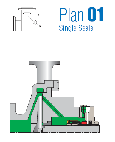
Plan 01: This is an internal recirculation from the pump discharge into the seal chamber. Plan 01 is recommended to be used for clean pumped products, since dirty products can clod the internal line. It is not recommended for vertical pumps. Its advantages are the following: product contamination is avoided and no external piping is needed, something advantageous especially for operation under low ambient temperatures (risk of freezing).
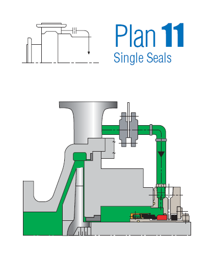
Plan 11: One of the most widely used flush plans nowadays. Plan 11 takes fluid from the pump discharge or from an intermediate stage and directs it to the seal chamber through a properly designed orifice (the side stream should have a slightly bigger pressure than the prevailing pressure directly behind the pump impeller) for cooling and lubrication of the seal faces. Similar to Plan 01, product contamination is avoided, whereas interconnecting piping is relatively easy to install.
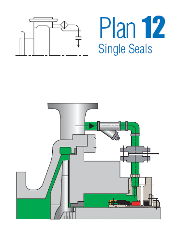
Plan 12 Plan 12 is similar to Plan 11, with the exception that a strainer of filter is added to the flush line for protection of the seal surfaces. A differential pressure indicator or alarm is employed so as to warn the user that the strainer or filter has been clogged.
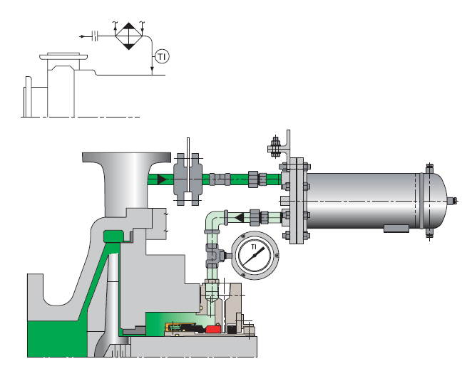
Plan 21: Plan 21 is a cooled version of Plan 11. A heat exchanger is installed between the pump discharge and the pressure-reducing orifice for lowering the sealing fluid temperature. Cooling provides lubrication and minimises the possibility of vaporisation in the seal chamber. However, due to the big thermal load applied on the heat exchanger, Plan 21 is not frequently used today. It is usually replaced with flushing Plan 23.
Plan 23: Plan 23 is similar to Plan 21. It is generally preferred for hot water services, especially boiler feedwater. It is more efficient to Plan 21
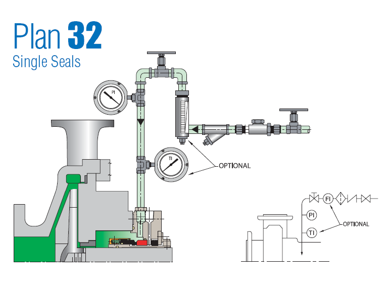
Plan 32: Plan 32 uses an external flushing stream. When properly selected, this flushing stream can result in extended seal lifetime.
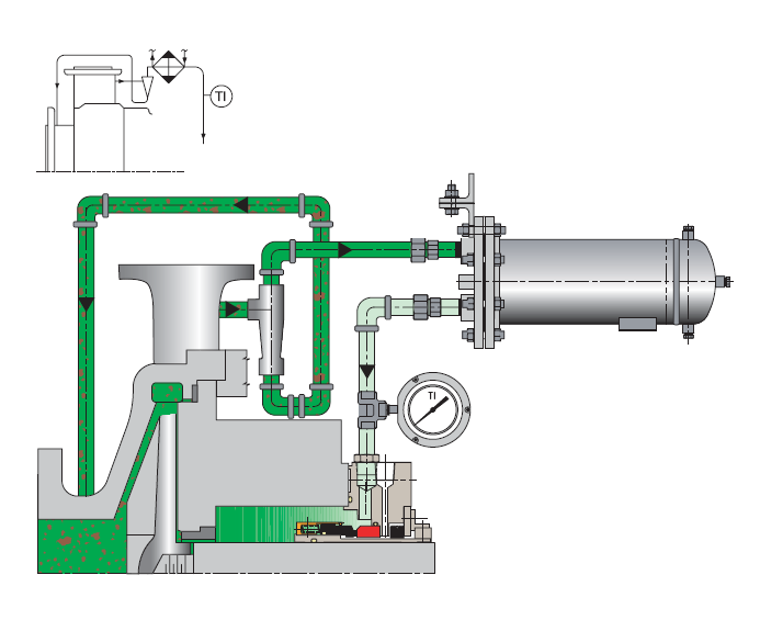
Plan 41: In Plan 41, product from pump discharge passes through a separator and then through a heat exchanger before being introduced to the seal chamber. This is typically used for hot services with solids.
Plan 62: With Plan 62, an external fluid stream is brought to the atmospheric sdide of the seal faces using a quenching gas. Quenching gas can be either steam, nitrogen or water. Typical applications include the following: steam quenching on hot surfaces to delay coking, nitrogen quenching on cold or cryogenic service for prevention of icing, water quenching for prevention of crystallisation. One of the dissadvantages of Plan 62 is the inefficient use of water.
Plan 65: Plan 65 uses a level switch installed at a reservoir for initiating an alarm when excessive leakage is detected. This way, equipment can be shut down in case of excessive seal leakage. This system also includes a loop that allows to bypass the orifice: this way, high pressure on the amtospheric side of the seal is avoided.