Electrical equipment used in any substation depends upon the following factors:
- Type of electrical substation- whether it is a Generating station, Transformer sub-stations, Switching Sub-stations etc.
- Design of the Substation,
- Service requirement
- Degree of protection required
However, in general, any typical sub-station has the following main equipment
- Generator ( generators are present only where electricity is generated i.e. only in generating station)
- Isolators or (Isolating Switches)
- Bus-bars
- Circuit breakers
- Power Transformers
- Instrument transformers (current and potential transformers)
- Insulator
- Reactors
- Lightning arrestors
- Metering and Indicating Instruments (like volt meters, ammeters etc.)
- Miscellaneous equipment (like fuses, auxiliary supplies etc)
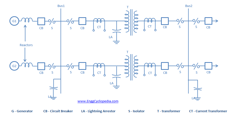
A typical layout of an electrical substation is shown below with the help of single line diagram:
Generators
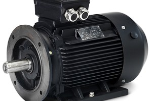
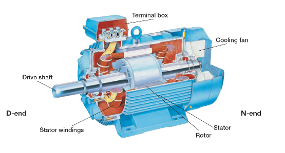
An electrical generator is one of the most important equipment. It generates electricity by converting mechanical energy of the prime mover into electrical form. It works on the principal of electromagnetic induction.
A generator consists of basically two important parts called as a stator and a rotor. The stator is the fixed part while the rotor is the rotating part. The stator consists of stator core on which a 3-ph electrical winding is wound. The rotor is rotated through a shaft by a prime mover (like for e.g. Steam turbine). This rotating rotor carries field winding or magnets which produce rotating magnetic flux. This rotating magnetic flux gets liked with the stator winding and emf gets induced in the stator winding. Thus electricity gets generated and is then later transmitted wherever required.
Isolators or Isolating switches:
In sub-stations, it is often desired to disconnect a part of the system for general maintenance and repairs. This is accomplished by an isolating switch or an isolator. An isolator is essentially a knife switch and is designed to open a circuit under no load. In other words, isolator switches are operated only when the lines in which they are connected carry no current. They also facilitate redistribution of loads.
Bus-bars
They are like electrical junction where electricity is collected from incoming transmission lines and then redistributed to the outgoing transmission line. All the important equipment in a substation are connected to the bus-bars, hence bus-bar protection is of outmost importance. If any fault occurs on the bus-bar then all other equipment in a substation connected to it might get affected and hence they must get tripped as soon as possible.
A substation can have more than one bus-bar housed in it. There are several bus-bar arrangements that can be used in a sub-station. The choice of a particular arrangement depends upon various factors such as system voltage, position of sub-station, degree of reliability, cost etc.
Circuit breaker
A circuit breaker is a protective device meant for breaking an electrical circuit during a fault condition. It is basically a type of automatic switch when the relay detects a fault condition it sets the circuit breaker into action and the circuit breaker has to break the circuit within minimum time, in order to quickly eliminate the source of fault. Once the fault is restored the circuit breaker can again make the circuit either manually or remotely.
A circuit breaker is used to open the circuit under normal condition as well. An isolator however cannot be used to open a circuit under normal conditions. It is because it has no provision to quench the arc that is produced during opening operation. Hence the use of circuit breaker is essential. The heaviest duty circuit breaker has to interrupt a short-circuit current of more than 100 kA
Power transformers
During transmission and distribution of electricity one needs to increase or decrease its voltage to ensure proper transmission and distribution with minimum power loss. This work is achieved with the help of power transformers. A power transformer is used in a sub-station to step-up or step-down the voltage.
A step up transformer steps up the voltage or increases the voltage. It is also sometimes referred as transmission transformer. It is used to step-up generation voltage to a high value (say 132 kV or 220 kV or more) for transmission of electric power.
A step down transformer steps down the voltage or decreases the voltage. It is also sometimes referred as Distribution transformer. It is used to step-down the voltage from values like 132 kV or 220 kV to voltage levels like 11 kV, 22kV or 33 kV. Except at the generating station, all the subsequent sub-stations use step-down transformers to gradually reduce the voltage of electric supply and finally deliver it at utilization voltage.
Instrument transformers
The lines in sub-stations operate at high voltages and carry current of thousands of amperes. The measuring instruments and protective devices are designed for low voltages (generally 110 V) and currents (about 5 A). Therefore, they will not work satisfactorily if mounted directly on the power lines. This difficulty is overcome by installing instrument transformers on the power lines. The function of these instrument transformers is to transfer voltages or currents in the power lines to values which are convenient for the operation of measuring instruments and relays. There are two types of instrument transformers viz.
- Current transformer (C.T.)
- Potential transformer (P.T.)
(i) Current transformer (C.T.)
A current transformer in essentially a step-up transformer which steps down the current to a known ratio. The primary of this transformer consists of one or more turns of thick wire connected in series with the line. The secondary consists of a large number of turns of fine wire and provides current for the measuring instruments and relays a current which is a constant fraction of the current in the line. Suppose a current transformer rated at 100/5 A is connected in the line to measure current. If the current in the line is 100 A, then current in the secondary will be 5A.
(ii) Voltage transformer.
It is essentially a step down transformer and steps down the voltage to a known ratio. The primary of this transformer consists of a large number of turns of fine wire connected across the line. The secondary winding consists of a few turns and it provides voltage for measuring instruments and relays a voltage which is a known fraction of the line voltage. Suppose a potential transformer rated at 66kV/110V is connected to a power line. If line voltage is 66kV, then voltage across the secondary will be 110 V.
Insulators
The overhead transmission lines and Bus-bars are supported on towers. Since the towers are at ground potential. The lined must be insulated with the tower structures. Overhead line insulators are used to electrically separate the line conductors from each other and from supporting structures. The most commonly used material for the manufacture of insulators is glass and porcelain. There are several types of insulators (e.g. pin type, suspension type, strain type, post insulator etc.) and their use in the sub-station will depend upon the service requirement
Reactors
In large capacity installations short circuit currents can attain such high values that unless certain means are used to limit them it becomes very difficult for the electrical equipment installed to withstand such high current levels. For this purpose auxiliary inductive devices called as reactors are introduced in each phase of the given installation.
Reactors are also used for power factor correction. If a transmission line has a load with poor power factor, reactors would be connected at the receiving end to correct the power factor.
Lightning arrestor
A lightning arrestor is another important protective device installed in the substation as well as on overhead transmission lines. As the name suggest it protects the electrical network from the damaging effects of lightning.
A lightening arrestor has two terminals high voltage terminal and one ground terminal. The high voltage terminal is typically connected to the overhead line or to the equipment to be protected. The ground terminal is connected through path of low resistance to ground. Between the high voltage and ground terminal there is either air or a material of high resistance. This material prevents the normal electrical power from being redirected to the ground. However when a lightning strikes it has very high current, and only this high current can cross the region of high resistance, thus diverting the strike away.