Impedance
What is it?
For any circuit impedance is defined as opposition to the flow of current in that circuit.
The unit of impedance is same as resistance i.e., (Ω). In a sense it is looked upon in the same way as resistance, but is slightly more complex than resistance since it depends upon frequency of the power.
Unlike Resistance, Impedance is not a scalar quantity but a vector quantity.
In any particular electrical circuit there can be resistive, inductive and capacitive components present in that circuit. The inductive and capacitive components offer inductive and capacitive reactance to alternating current. Reactance is also measured in Ohms (Ω).
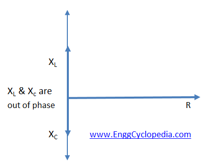
XL (inductive Reactance) and XC (capacitive Reactance) are vector quantities and are always in phase opposition to each other, hence they will tend to cancel out each other
The total reactance of RLC circuit can be given as
(Reactance (X)) = (inductive Reactance (XL) - capacitive Reactance (XC))
Now impedance of a circuit is the defined as opposition to the flow of alternating current, hence impedance (Z) of a circuit is the vector addition of total resistance and total reactance of that circuit.
Impedance (Z)= Resistance (R) + j(Reactance (X))
Z = R + j(XL - XC)
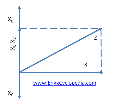
Since XL and XC are vector quantities in phase opposition to each other they will tend to cancel out each other
Perfectly balanced circuit:
A perfectly balanced circuit is the one which has equal capacitive reactance and inductive reactance. Consider circuit given below
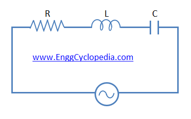
Here as XL and XC are equal and will cancel out each other rendering the circuit purely resistive.
XL = XC
XL - XC = X = 0
Therefore Z= R+jX=R+j0=R