In process industries, pumps are mechanical devices used to move fluid from one place to another place. It is very important to understand the P&ID arrangement for pumps, as they are the most basic and widely used equipment in process industries and piping and instrumentation diagrams.
Table of content:
Pump P&ID arrangement
Guidelines to prepare P&ID for pumps
Pump P&ID arrangement

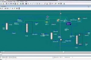
The diagram from above is a typical representation of P&ID or Piping & Instrumentation Diagram of a pump.
Guideline to prepare a P&ID for pumps
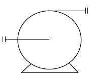
Selection of pump symbol
The selection of a pump symbol in a P&ID arrangement depends on the type of pump being used. Proper pump symbol should be selected first of all, as shown in the presented drawing. This should be selected from the list of equipment symbols on the legend sheets of a particular project.
Nozzles
All the nozzles on the pump should then be correctly represented with size and flanges. This includes inlet and outlet nozzles and casing drains and vents as shown in the sample drawing presented here. Generally, the suction and discharge nozzles on the pump are smaller than suction and discharge line sizes. Appropriate reducer / expander to be clearly indicated in such cases.
Inlet / Outlet lines
Inlet and outlet lines are the next to be drawn up. Line number, material class, size etc. is to be correctly assigned to each of the lines in the pump P&ID. Properly identifying and representing the inlet and outlet lines, along with other associated components, is crucial to the safe and efficient operation of pump systems.
Isolation valves, spectacle blinds, spacers
Isolation valves, spectacle blinds, spacers etc. to be used for maintenance should be drawn up next on the inlet / outlet lines. The isolation valves on suction and discharge lines should be 'Locked Open' in case of automatic pump start-up.
Isolation valves are used to shut off the flow of fluid to or from the pump. They can be located on both the inlet and outlet lines and can be manually operated or automated. Spectacle blinds are used to temporarily block the flow of fluid in a piping system. Spacers are used to separate flanges and provide room for maintenance activities. They are typically used between flanges on the inlet and outlet lines of a pump.
Strainer
Pump inlet line in the P&ID diagram is to be fitted with a strainer for pump protection. This strainer can be equipped with a pressure differential gauge to monitor blockage in the strainer.
A strainer is typically installed in the suction line before the pump to protect the pump from any foreign particles or debris that may be present in the fluid.
Instrumentation
Pressure gauges are normally to be provided on suction and discharge of the pump. In addition, pressure transmitters connected to Emergency Shutdown (ESD) system can also be provided as per requirements.
Temperature gauges and transmitters to be provided as per requirements for operating and controlling the equipment.
Valves
A check valve should be normally provided on the pump discharge to avoid reverse flow when the pump is not in operation.
Downstream to the check valve on the pump discharge, minimum flow recirculation line for the pump needs to be provided. A flowmeter should be provided before the minimum flow line, as shown on the presented sample drawing.
A flow control valve with or without bypass is then to be provided on the minimum flow recirculation line. The isolation valves for this control valve need to be locked open or sealed open and the FCV should be of 'Fail Open' type. The minimum recirculation line is normally routed back to the suction vessel of the pump.
Vents & Drains
Drains and vents to be provided on the suction / discharge lines, minimum flow line and on pump casing, so that the pump and associated piping can be completely drained for maintenance.
Utility connection
For purging the pump with nitrogen, a connection should be provided right after isolation valve on the suction line. This connection can also be used as a drain.
All the guidelines given here are very general and may be modified as per specific requirements of any particular project.
These are general design guidelines for a pumping system, applicable even outside the scope of simply creating a piping & instrumentation diagram for a pump.