Vapor Compression Refrigeration uses mechanical energy by repeating compression and expansion of coolant fluid to achieve cooling by Joule–Thomson effect. A majority of big refrigeration systems in use nowadays use the Vapor Compression Refrigeration (VCR) cycle.
Vapor compression refrigeration cycle is widely used in the air conditioners, heat pumps and HVAC systems.
Table of Content:
1. What is VCRS (Vapor Compression Refrigeration System)?
2. Typical Vapor Compression Refrigeration Cycle Diagram
3. Stages of Vapor Compression Refrigeration Cycle
3.1. Evaporation Stage of refrigeration
3.2. Compression of the refrigerant
3.3. Condensation of pressurized refrigerant
3.4. Expansion of the subcooled and highly pressurized refrigerant
What is VCRS (Vapor Compression Refrigeration System)?
Vapor compression refrigeration system (VCRS) is a type of refrigeration system that uses a vapor compression cycle to transfer heat from a lower temperature region to a higher temperature region. It is commonly used in air conditioning systems, refrigerators, and industrial refrigeration applications.
The basic components of a VCRS include a compressor, a condenser, an expansion valve, and an evaporator. The refrigerant, which is typically a gas, is compressed by the compressor and then circulated through the condenser where it releases heat and condenses into a liquid. The liquid refrigerant then passes through the expansion valve where it expands and evaporates into a gas. During this process, it absorbs heat from the surroundings, which cools the area.
The evaporator then transfers the refrigerant back to the compressor where the process is repeated. The VCRS can be used for both cooling and heating applications by simply reversing the direction of the refrigerant flow. Overall, the VCRS is an efficient and reliable way to provide cooling or heating for various applications.
Typical Vapor Compression Refrigeration Cycle Diagram
We will try to present below the basic characteristics of VCR cycle:
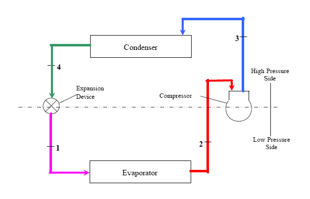
Figure 1 - Typical schematic of a Vapor Compression Refrigeration (VCR) cycle
Stages of Vapor Compression Refrigeration Cycle
Evaporation Stage of refrigeration
From points 1 to 2 on figure-1, low-pressure liquid refrigerant in the evaporator absorbs heat from its surrounding environment, usually air, water or some other liquid and gets evaporated into gas. As such, the refrigerant is slightly superheated at the outlet of the evaporator. The evaporating liquid absorbs heat from the surroundings, thus performing the cooling or refrigeration duty for the surrounding air, water or other medium. This is where the refrigeration actually occurs.
Compression of the refrigerant
From point 2 to 3 on figure-1, the superheated vapor from evaporator enters the compressor where its pressure is increased due to compression. The temperature also typically increases, since a part of the energy put into the compression process is transferred to the refrigerant.
Condensation of pressurized refrigerant
From point 3 to point 4 on figure-1, the pressurized and superheated gas from compressor outlet is sent to a condenser. The initial part of the cooling process (3-3a in figure-2) de-superheats the gas before it is then turned back into liquid (3a-3b in figure-2). The cooling for this process is usually accomplished by use of air or water. A further reduction in temperature happens in the pipe work and liquid receiver (3b-4 on figure-2), so that the refrigerant liquid is sub-cooled as it enters the expansion device. This step is where the heat absorbed from process fluid at the evaporation stage is vented out to atmosphere, as indicated in figure-2.
Expansion of the subcooled and highly pressurized refrigerant
From point 4 to point 1 on figure-1, The high-pressure sub-cooled liquid passes through the expansion device, which reduces its pressure as well as controls the flow into the evaporator. The process is repeated from now in cycle.