It is very important to know pumps / compressors P&ID symbols to read P&ID diagrams. P&ID diagrams, also known as Piping and Instrumentation Diagrams, are used to map out the design of engineering systems in various industries. These diagrams are essential for problem identification and troubleshooting, as they provide a clear representation of the system's components and their interconnections.
Commonly used P&ID (Piping and Instrumentation Diagram) symbols for pumps / compressors. Note that they may differ slightly from one project to another.
Table of content:
Pumps P&ID symbols
Compressors P&ID symbols
Pumps P&ID symbols
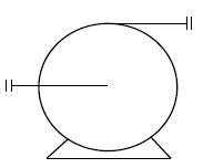
The symbol for a centrifugal pump typically consists of a circle with two connecting lines. The circle represents the housing of the pump and it includes impeller of the pump, which rotates to generate the flow. Two lines represent suction and discharge flow connections.
Dosing pump
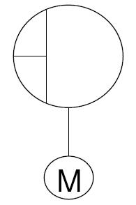
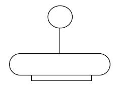
A dosing pump sucks a predetermined amount of liquid into the pump chamber and adds the liquid to a process. The pump is driven by an electric motor. Larger circle represents the casing of the pump and smaller circle is motor attached to it.
Gear pump
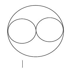
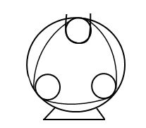
P&ID symbol of gear pump consist of two small circles inside one big circle. Outer circle represents casing and two small circles represents gear. Line outside bigger circle represents inlet connection.
Vane pump
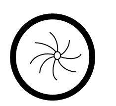
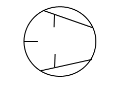
A vane pump p&id symbol typically consists of an oval or circle shape that is connected to the inlet and outlet piping. The oval or circle shape represents the body of the pump, while the inlet and outlet connections indicate the flow of fluid into and out of the pump. Within the oval or circle shape, lines represent the rotor and vanes.
Vertical pump
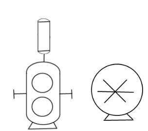
Vertical pumps are made up of a motor, discharge head, and at least one rotating impeller that is attached to a shaft that directs water into a diffuser casing called a bowl. The symbol consists of a cylinder shape with an arrow pointing upward, which represents the body of the pump.
Metering pump
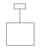
P&ID symbol of metering pump has two rectangles, one big and other small. Larger rectangle represents pumping chamber and smaller rectangle represents piston to displace the fluid in the chamber.
Cavity pump
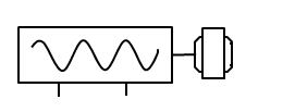
It transfers fluid by means of the progress, through the pump, of a sequence of small, fixed shape, discrete cavities, as its rotor is turned. In given schematic of p&id symbol of cavit pump, shape inside rectangle shows helical rotor.
Horizonal pump
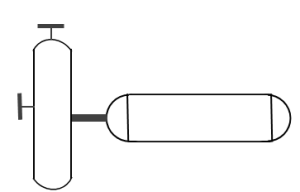
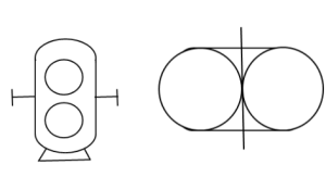
Horizontal pumps are a design where the pump head is located adjacent to the motor on a horizontal plane. In P&Id symbol first cylinder represent pump head while other represents motor.
Peristaltic pump
The peristaltic pump has two primary components: the motor and tube. A motor turns wheels inside of a tube that rotates. The motor presses the tubing against the outer portion of the housing. As it does that, the motor pinches the tube and creates a space where it draws in liquid.
Positive displacement pump
A positive displacement (PD) pump moves a fluid by repeatedly enclosing a fixed volume and moving it mechanically through the system. The pumping action is cyclic and can be driven by pistons, screws, gears, rollers, diaphragms or vanes. In two symbols given here, one represents gears and other represents vanes.
Turbine pump
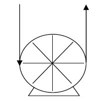
Turbine pumps are special types of centrifugal pumps which use turbine-like impellers with radially oriented teeth to move fluid. The main difference between a turbine pump and a typical centrifugal pump is its impeller design and it can be seen in P&ID symbol.
Vacumm pump
A vacuum pump is a type of pump device that draws gas particles from a sealed volume in order to leave behind a partial vacuum. It is a piece of equipment capable of generating a partial or low-pressure vacuum by pushing gas or air molecules out of a sealed chamber.
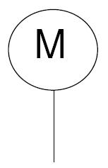
Motor
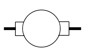
In P&ID symbol of motor circle represents body of the motor and line connected shows shaft.
Click on the link to check the post on Typical P&ID arrangement for pumps.
Compressors P&ID symbols
Centrifugal compressor
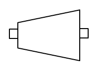
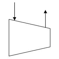
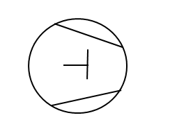
In p&id symbol of centrifugal compressor trapezoidal represents casing of the compressor which consists of diffuser and rotating impeller. Outer connections and lines represent inlet and outlet connections.
Trapezoidal shape is a casing of axial compressor. It consists of shaft, fixed blades and moving blades.
Selectable compressor
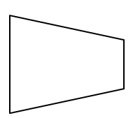
A selectable compressor is a type of air compressor that allows you to choose the level of compression that you need for a particular task. This is achieved by providing multiple stages of compression in a single compressor. P&ID symbol of selectable compressor is simple of trapezoidal shape.
Diaphragm compressor
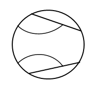
Diaphragm compressors move and compress gas using a set of three, flexible diaphragm membranes. Gas enters the compressor’s process head from an external tank or process on its down-stroke. On the up-stroke, the diaphragms flex, reducing the area inside the chamber, pushing the gas out of the compressor and on to the process/application. The curved line represents the diaphragm in the compressor.
Ejector compressor
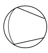
The ejector in ejector compressor uses a converging nozzle to increase the fluid velocity, which converts the pressure energy of the highpressure fluid into kinetic energy. It can be seen from schematic that two semicircle inside bigger circle represents nozzle.
The liquid-ring pump compressor compresses gas by rotating a vaned impeller located eccentrically within a cylindrical casing. Impeller can be seen from schematic inside a circle which represents cylindrical casing.
Piston compressor
The basic idea behind the symbol is to represent a device that compresses air or gas using a reciprocating piston. Piston can be seen in given p&id symbol inside the circle.
A reciprocating compressor is a positive-displacement machine that uses a piston to compress a gas and deliver it at high pressure. Reciprocating Compressor has piston, cylinder, inlet valve, exit valve, connecting rod, crank, piston pin, crank pin and crank shaft.
Ring compressor
A ring compressor is a compressor that features pistons fit inside of a cylinder using compression rings that seal between the piston and cylinder wall.
Reciprocating compressor
A reciprocating compressor is a positive-displacement machine that uses a piston to compress a gas and deliver it at high pressure. Reciprocating Compressor has piston, cylinder, inlet valve, exit valve, connecting rod, crank, piston pin, crank pin and crank shaft.
Screw compressor
A screw compressor is a type of rotary compressor that uses two interlocking screws to compress refrigerant gas. The screws are meshed together, and as they rotate, they trap refrigerant gas between them and reduce the volume of the gas, increasing its pressure and temperature. P&ID symbol of screw compressor is showed in schematic.
Roller vane compressor
Roller vane compressor consists of vanes mounted to a rotor that rotates inside a cavity. The vane-type compressor consists of a cylindrical rotor with longitudinal slots in which radial sliding vanes are fitted. Vanes are represented by vertical and horizontal lines inside the circle in P&ID symbol.
Air compressor
An air compressor is a pneumatic device that converts power (using an electric motor, diesel or gasoline engine, etc.) into potential energy stored in pressurized air (i.e., compressed air).
Check this post to study typical P&ID arrangement of centrifugal compressor system.
