Velocity seal or buoyancy seals are used to reduce prevent air ingress in the flare stack used in oil and gas processing facilities.
Air ingress in flare network
Typically the flare/vent network along with the vent KO drum operates at a low pressure close to atmospheric pressure. This pressure is actually the built-up back pressure due to the continuous flared or purged gas flow in the vent stack. Pressure at the vent stack tip is atmospheric and back-pressure in the knock out drum is atmospheric pressure plus the frictional pressure drop from continuous venting/purging of the gas.
If the flow of gas to vent/flare stack stops for some reason, there is a possibility of air ingress into the flare stack and into the vent KO drum, vent network. This can result in an explosive mixture of air and hydrocarbons in the vent/flare network, which can be catastrophic. To avoid air ingress into the flare network, a minimum continuous flow of purge gas is needed.
To reduce the minimum requirement of purge gas flow, velocity seal or buoyancy seal can be used at the base of a flare stack.
Buoyancy Seal
Figure 1 - Schematic of a buoyancy seal in a flare stack indicating purge gas path
Buoyancy seal typically uses the difference in densities of the purge gas and ambient air to keep the air from entering flare system. Buoyancy seals use a couple of concentric baffled cylinders in the path of the purge gas as indicated in figure-1. If purge gas is lighter than air it accumulates at the top of the inner cylinder and forms a seal to prevent entry of air into the flare system. If the purge gas is heavier than air then it accumulates the bottom of the outer cylinder and forms a seal there to prevent air from entering flare system. In either way air has to face an obstacle before it can enter the flare system, as it has to travel once upward and once downward in the buoyancy seal. Buoyancy seal normally reduces purge-gas velocity requirement through the tip to 0.003 m/s. But much higher gas exit velocities are needed to avoid the burn back of the flare tip.
One drawback of using a buoyancy seal is possibility of liquid accumulation in the bottom of the outer cylinder. Hence a provision of a drain connection is needed to drain the liquids when they accumulate.
Another major drawback is if the flare tip is lined with refractory material. In this case the debris falling from flare tip refractory can get trapped in the buoyancy seal creating a potentially hazardous operating scenario.
Velocity Seal
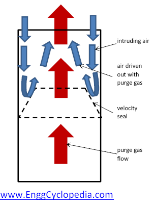
Figure 2 - Velocity seal for purge reduction
Velocity seals work bases on the premise that when air infiltrates the flare tip, it tends to hug the inner walls of the flare tip. As indicated in the figure-2, a velocity seal is a cone-shaped obstruction placed inside the flare tip so as to obstruct the infiltrating air from ‘hugging the inner wall’. The purge gas flow coming through the cone is a focused stream which sweeps away the infiltrating air along with it. This seal normally reduces the purge gas velocity through the tip to between 0.006 m/s to 0.,012 m/s and manages to keep the oxygen level below the seal under 4-8% level. However purge gas requirement to prevent the burn back of the flare tip is much higher than this.

