Surface area available for heat transfer is quite an important determinant of the overall heat transfer. Finned tube exchangers are known for maximizing heat transfer surface area, by design.
Finned tube heat exchangers have tubes with extended outer surface area or fins to enhance the heat transfer rate from the additional area of fins. Finned tubes or tubes with extended outer surface area enhance the heat transfer rate by increasing the effective heat transfer area between the tubes and surrounding fluid. The fluid surrounding finned tubes maybe process fluid or air.
Table of content:
1. Types of finned tubes
1.1. Longitudinal finned tubes
1.2. Transverse finned tubes
2. Design of finned tube heat exchangers
3. Applications of finned tube heat exchangers
Types of finned tubes
Longitudinal finned tubes
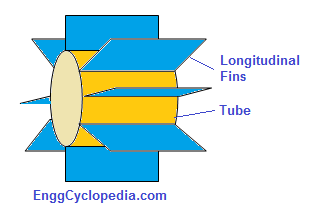
Figure 1 - Longitudinally finned tube in heat exchanger
Longitudinal fins on a tube are best suited for applications where the flow outside the tubes is expected to be streamlined along the tube length, for example double pipe heat exchangers with highly viscous fluid outside the finned tube.
Longitudinal fins on a tube run along the length of the tubes. The cross sectional shapes of longitudinal fins can be either flat or tapered. For different cross sectional geometries, various correlations are available in the literature to evaluate the heat transfer coefficients on outer side of the tubes.
Transverse finned tubes
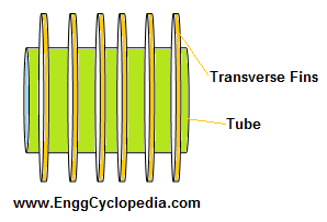
Figure 2 - Transversely finned heat exchanger tube
Transverse fins are normally used for gas flows or turbulent flows and for cross flow type exchangers or shell and tube heat exchangers. For air coolers, tubes with transverse fins are best suited.
Transverse fins are hollow metal discs spaced from each other and fitted along the length of the finned tubes. The transverse fin discs can be flat or tapered. Heat transfer coefficients on the surface of the fin depend on the fin disc geometry and are available in the literature in the form of correlations.
Design of finned tube heat exchangers
To design finned tube heat exchangers for enhanced heat transfer area, heat calculation of required heat transfer area and optimum spacing of tubes to create the required surface area are two parts of the problem. Increased heat transfer area can mean increase in the heat exchanger efficiency.
Heat transfer coefficients at surfaces inside and outside the tubes are calculated using experimentally determined correlations. The heat transfer efficiency of fins is calculated using correlations. Different sets of correlations are available for calculation of fin heat transfer efficiencies of longitudinal and transverse fins. The fin area multiplied by fin heat transfer efficiency and added to bare tube area, gives the effective outer heat transfer area.
Overall heat transfer coefficient is obtained by adding the heat transfer resistances evaluated at outer and inner surface areas of the tube. For outer area, value of the effective area is used. Finally the total heat transfer area required and hence required number, length etc. of tubes is calculated.
Effect of number of tubes on the outer fluid flow is checked for changes in fluid velocity. If velocity of outer fluid changes significantly, the heat transfer coefficients and required tube area is reevaluated. Thus in a few such iterations, optimum arrangement of finned tubes, to obtain the desired heat transfer area can be determined.
Applications of finned tube heat exchangers
Finned tube heat exchangers are preferred when you have a low heat transfer coefficient on the outside of the tubes. In such cases the extra heat transfer area created by the fins helps in ensuring that required rate of heat transfer is made possible.
Common applications involve air on the outside and a liquid in the inside of the tubes.
