Control valves are mechanical devices used to regulate and control the flow of fluids, such as gases, liquids, or steam, through a pipe or other conduit. They are used in a variety of industries, including oil and gas, chemical processing, power generation, and water treatment.
Table of content:
1. What Are Control Valves?
2. How Do Control Valves Work?
3. Control Valve Characteristics
4. Types of Valves
5. Sizing of Control Valves
6. Parts of Control Valves
7. Control Valves Applications
8. Selection of Valves
9. Control Valve Troubleshooting Guidelines
10. Valve P&ID Symbols
11. Control Valves P&ID Arrangement
12. Typical Control Valve Datasheet
13. Types of Valve Actuators
What Are Control Valves?
Control valves are elements used in process control loops to adjust process variables such as flow, liquid levels, pressure, temperature etc. Control valves maintain the desired operating conditions such as flow rate, level, temperature and pressure required for the efficient operation of the process plant.
Control valves essentially consist of a valve and an actuator, more valve control elements may also be present in certain cases. Control valves work by opening or closing to regulate the flow of fluid through a pipe. They are typically controlled by an actuator that responds to a signal from a controller, such as a flow meter, pressure sensor, or temperature sensor.
These valves achieve the desired controlling effect essentially by throttling the flow.

How Do Control Valves Work?
The control valve contains two major components. One is the valve body that actually controls the flow of fluid. Actuator is another major part that moves valve body either manually or by using electric, pneumatic or a hydraulic signal.
The control valve opens and closes to regulate the flow of fluid through a pipe. Actuator receives signal from a controller such as flow meter, pressure sensor or temperature sensor and controls the valve body according to received signal from a controller. This process continues until the process variable reaches desired set point or comes within the desired operating range.
Check how different types of control valves work in the below given posts.
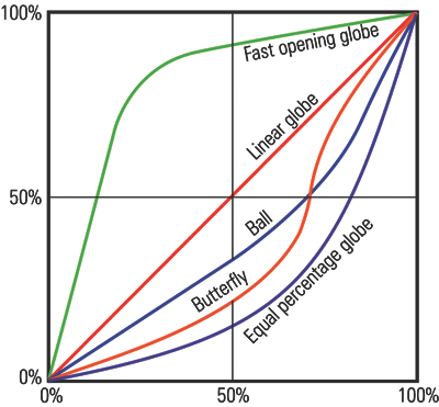
Control Valve Characteristics
The relationship between the control valve opening (also known as ‘valve travel’) and the flow through valve is known as the flow characteristic of that valve. An inherent flow characteristic is the relation between valve opening and flow under constant pressure conditions.
The gain of a valve is defined as the change in flow per unit % change in the valve opening.

- The linear flow characteristic has a constant slope, meaning that valves of this type have constant gain through complete range of flows. These valves are often used for liquid level control and certain flow control operations requiring constant gain.
- Equal percentage valves are known by that name because whenever the valve opening is changed, the percentage change in flow is equal to percentage change in the valve opening. This means the change in flow proportional to the flow just before the incremental valve opening is performed. This can also observed in the following figure. This type of valves is commonly used for pressure control applications. They can be considered for applications where high variations in pressure drop are expected.
- Quick opening type of valves does not have a specific mathematical definition. These valves give a large increment in flow for relatively smaller valve opening, as can be observed in the following figure. These valves usually find use for on-off service applications.
- Modified parabolic valves lie somewhere between the linear valves and equal percentage valves. As can be observed in the following figure, they can be used for throttling at low flow levels and have almost linear characteristics at higher flows.
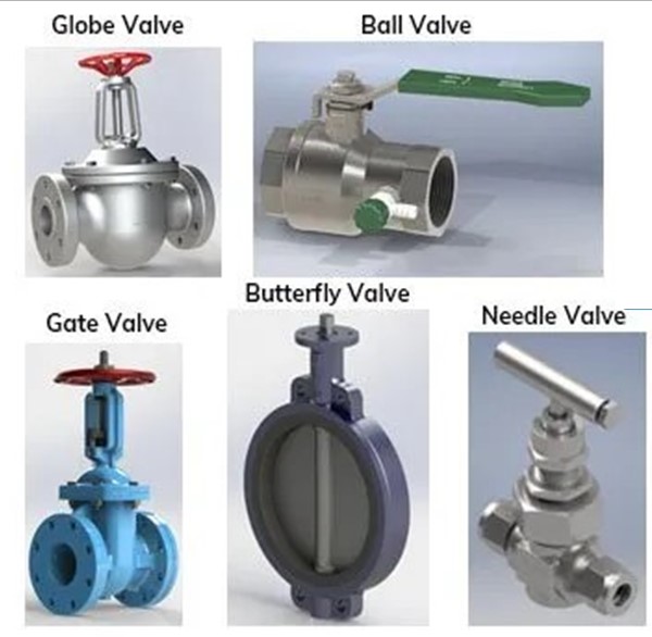
Types of Valves
Valves can be broadly categorized based on the type of stem movement – linear or rotary type.
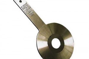
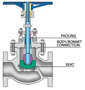
Globe valve
Globe valves are most commonly used liner stem motion type control valves. The flow control for this type of valves is achieved by motion of a plug as shown in the following figure. The shape and type of the plus also determines the valve flow characteristics.
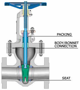
Gate valve
Gate valves use linear type of stem motion for opening and closing of valve. These valves use discs as closure member, as can be seen in the following figure. The faces of this disc can be either parallel or the disc can be wedge shaped.
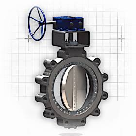
Butterfly Valve
Butterfly valves are known for their compact size and low initial costs, which is primarily due to the small wafer and body size of these valves and the simplicity of this design. This valve belongs to the rotary stem motion type of valves.
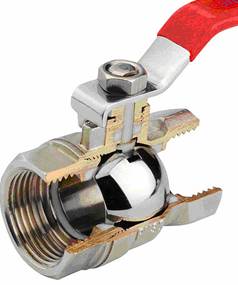
Ball valve
These valves use a spherical shaped closure member with a cylindrical bore through the member for passage of flow. This spherical closure member has to be rotated by 90 degrees to bring the valve from fully closed position to fully open position. This type gets the name from the shape of the closure member. If the diameter of the cylindrical bore is same as that of the connecting pipe, the valve is known as full bore valve. If this diameter is less than that of the connecting pipe, the valve is known venturi style valve. These valves rotary stem motion.
Click the button and check the given guide for details on types of control valves. Also study the use of different type of valves as control valves based on application as well as services and caution where not to use it.
Sizing of Control Valves
The orifices of control valves can be adjusted to control the flow through them. Control valve sizing and selection is based on a combination of theory and empirical data. The capacity, characteristic, rangeability and recovery are four important elements for selection of a control valve. Cv is known as flow coefficient or orifice coefficient of a valve. This coefficient Cv is related to the flow and pressure conditions by the following basic liquid equation.

Hence,

The required Cv for a valve can thus be calculated based on flow and pressure conditions. This Cv should then be matched to that of the available valves and a suitable valve should be selected so that the required Cv falls between 70% to 90% of the selected valves Cv capability. The possibility of maximum and minimum process flows has also to be taken into consideration while selecting the valve.
Many flow cases may often fall outside the range of the basic liquid equation mentioned above for Cv calculation. For these cases a modified liquid equation for Cv calculation is given as,

The basic equation mentioned above for liquids is given below in the modified form for gases.

The capacity of a control valve is represented as,
Cd = Cv / d2 (d being the diameter of the valve)
Valve characteristic is the relation between valve opening (valve travel) and flow through the valve.
Rangeability of valve can be defined as the ratio of maximum to minimum flow over which good control can be achieved by using the valve.
Recovery is refers to the pressure recovery from the low pressure at vena contracta to the valve outlet. Pressure recovery is high for well streamlined valves.
Control valve sizing calculation is crucial for maintaining efficient and reliable industrial processes. By following the proper sizing process and selecting the appropriate valve type, engineers and operators can ensure the optimal performance of their industrial processes. This post contains a sample control valve sizing calculation which demonstrates steps to be followed when solving control valve sizing problem for flow control.
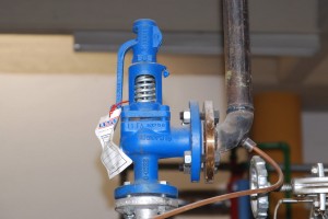
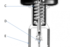
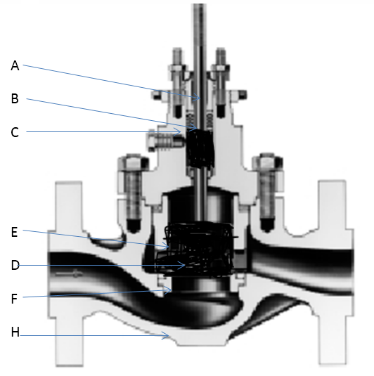
Parts of Control Valves
Control valves are typically composed of several key components that work together to control the flow of fluid in a system. Check the given post for detailed study on different parts of control valves.
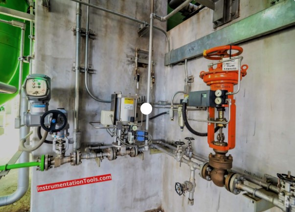
Control Valves Applications
In the Process industry whether it is oil and gas, refinery, petrochemical, chemicals, specialty chemicals, pharmaceutical, power etc., to control the process or process related utilities some control elements is required. Control valves play a crucial role in maintaining desired process conditions such as pressure, temperature, flow rate, and level in process industries. Check detailed post on control valve applications.
Selection of Valves
Different structures of different types of valves make them suitable for a wide range of applications. For each application some types of valves are more suitable compared to others. Check this post that lists some criteria for selection of valves that are most suitable for a given application or service.
Control Valve Troubleshooting Guidelines
Different structures of different types of valves make them suitable for a wide range of applications. For each application some types of valves are more suitable compared to others. Check this post that lists some criteria for selection of valves that are most suitable for a given application or service.
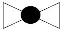
Valve P&ID Symbols
Study here various commonly used valve P&ID symbols (Piping and Instrumentation Diagram symbols) for manual valves such as gate valve, ball valve, plug valve, butterfly valve, 3 way valve, globe valve, check valve etc.
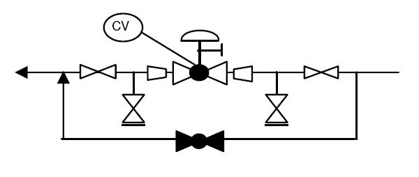
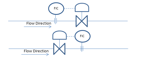
Control Valves P&ID Arrangement
Take a quick look at typical P&ID arrangement for control valves along with basic elements used in designing and operating control valves.
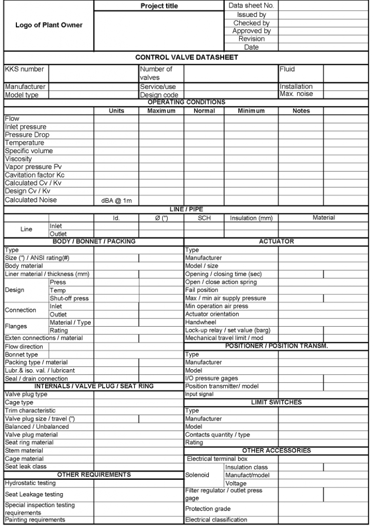
Typical Control Valve Datasheet
In order to be able to order the best control valve suited for the application, the user has to provide the valve manufacturer with all the necessary information to select and design a suitable control valve.
A typical control valve datasheet captures important parameters for its design and selection - like operating conditions, design conditions, line size, valve type, actuator type etc. This information help engineers and professionals make informed decisions.
Types of Valve Actuators
Control valve actuators are devices that are used to control the opening and closing of control valves in various industrial processes. These actuators are responsible for converting the control signal into mechanical motion, which then positions the valve accordingly. Check different types of valve actuators in this post.