This guest article was posted by the Engineering team at - Inveno Engineering.
The steam world continuously experiences reliability issues with electric condensate pumps that can be easily resolved with a proper understanding of the condensate system and by choosing the correct electric condensate pump system. The first step is to recognize that the world’s steam/condensate systems can be divided into two major categories: nonmodulating and modulating. The majority of the condensate pumps used in steam/condensate systems are for modulating steam systems. Selecting the wrong condensate pump system can lead to significant problems: unreliable electric condensate pumps can cause major issues with safety, reliability, production, optimization, energy, and loss of condensate (water).
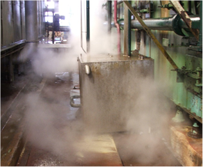 Figure 1: Electric condensate pump failure
The technical paper will discuss modulating steam systems and the correct methods for selecting an electric condensate pump. The electric condensate pump system is the most energy-efficient, reliable method for pumping condensate. Understanding the following points will provide the information needed to select the correct electric pump.
Determine the type of condensate system
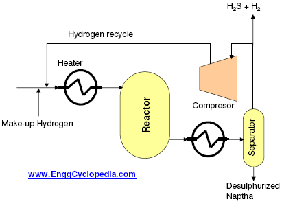
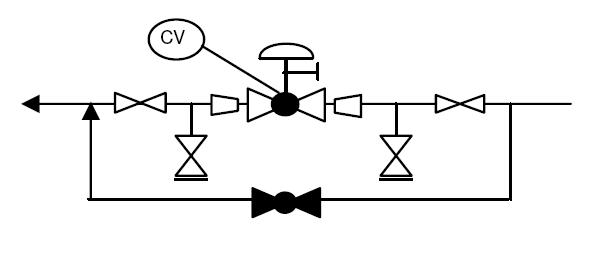
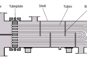
Modulating steam systems will have condensate/flash steam (two-phase flow) is being discharged from a steam/condensate process. Modulating steam system means the process application has a steam control valve modulating the steam to the process and the control valve can operate from 0% (closed) to 100% (full open) and anywhere in between. (See Figure 1.) Figure No. 1 indicates a shell and tube heat exchanger, but the example can be any steam process with a steam valve that can modulate to close to or 0 psig.
Examples of modulating steam processes;
- Any product temperature outlet temperature of 220oF or lower
The steam temperature at 0 psig is 212oF, so it will require very low steam pressures. A lot of process temperatures are at 180oF, such as CIP systems and process hot water systems.
The steam pressure after the steam control valve and before the process heat exchanger can vary (P2 reading) depending the process conditions. The pressure at P2 can range from the full line pressure being delivered to the steam control valve (P1) all the way down to a “0” pressure.
In this case, the condensate cannot discharge in the following ways;
- No elevation in piping after the discharge device (steam trap or condensate valve)
- The condensate line cannot be pressurized
Instead, the condensate flow from the steam process has to be discharged into a condensate line with pressure at 0 psig (P5) and delivered to a vented condensate receiver tank that is operating at or close to “0” pressure.
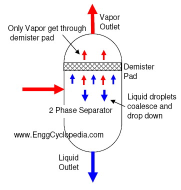
Figure 2 depicts the typical condensate receiver tank arrangement, where the flash steam is allowed to be vented to the atmosphere.
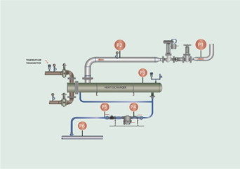 Figure 2: Steam control valve
Why does the condensate need to be pumped?
There are several reasons for the use of an electric condensate pump but only install a condensate pump if a condensate pump is needed. A percentage of condensate pumps installed are not needed and can be eliminated from the condensate system. The following examples of why a condensate pump is needed in the system.
- Condensate return piping elevations after the drain device (steam trap or control valve)
- Condensate return line pressures are higher than the steam pressure at the inlet of the drain device (steam trap or control valve)
- Condensate return line piping length or long distance back to the steam generation location
Simple Point, but one that is often forgotten “P1 or the inlet to the steam trap must always be higher than P2 the outlet of the steam trap”. If P2 is higher than P1, then condensate is not going to be removed from the process.
Determining the condensate temperature that needs to be pumped
Condensate returning to the condensate system as a two-phase flow (condensate/liquid and flash steam/vapor). Unless, the plant does not insulate the condensate line or condensate components, then the flash steam will be condensed to condensate and the result will be single phase (liquid) flow with an energy loss due to the uninsulated condensate system.
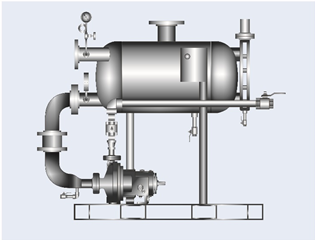
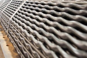
Figure 3: Standard electric condensate pump
However, the condensate system is usually insulated and there will be two phase flow back to the condensate tank. Therefore, the condensate temperature will be close to 212oF and that must be part of your selection process.
Condensate temperatures above 180oF; electric pump requires NPSH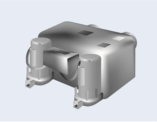
Figure 4: Low Condensate Temperature Electric Pump Unit
A critical factor that should be investigated in the selection of a condensate pump is the NPSH. Due to the two-phase flow (flash steam and condensate) which will keep the condensate temperatures close to 212oF will require NPSH to ensure no pump cavitation.
Figure No. 3: Is a low temperature condensate unit with a 180oF condensate temperature design; which is due to the insufficient NPSH to pump condensate above 180oF. Condensate is a gravity condensate system will be at or close to 212oF; therefore the condensate pump will cavitate during operation that develops into a un-reliable operation.
NPSH is determined by factors such as temperature, altitude, static head, and capacity. Condensate pumps are available that have been specifically designed to handle low NPSH, preventing cavitation, and thus able to operate at higher temperatures.
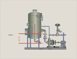
Figure 5: NPSH
Cavitation
As liquid enters the eye of the impeller in a centrifugal pump, its pressure is reduced. If the absolute pressure at the impeller eye drops down to the vapor pressure of the fluid, vapor pockets begin to form. As these vapor pockets travel in the fluid along the vanes of the impeller, pressure increases, and the pockets collapse.
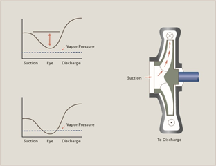
Figure 6: Pump cavitation
This collapsing of the steam bubbles is called cavitation.
Cavitation is not only noisy but also damages the pump impeller, shaft and seal, and, over time, may reduce pumping capacity. NPSH refers to the minimum suction pressure, expressed in feet of water column, that is required to prevent the forming and collapsing of these vapor pockets.
The diagram shows the change in system pressure (Ps) as the fluid travels through the impeller. To prevent cavitation, Ps must remain above the vapor pressure. The top curve shows system pressure (Ps) remaining above fluid vapor pressure as it passes through the pumps; cavitation cannot occur. The bottom curve shows Ps falling below the vapor pressure as it enters the impeller eye. This will cause cavitation. The cutaway view of a pump on the picture shows the passage of flow through the impeller.
NPSH is determined by factors:
- Temperature
- Altitude
- Static head
- Capacity
NPSH = Barometric Pressure, Ft. + Static Head on suction,ft. - friction losses in suction piping, ft. - Vapor Pressure of liquid, ft.
Defined as a suction pressure minus vapor pressure expressed in feet of liquid at the pump suction. Results from the height of water above the pump suction.
Suction Head = Total Pressure of Liquid Entering the Pump Suction
Two Values of NPSH
There are two values of NPSH: NPSHR and NPSHA.
NPSHR (required) is the amount of suction head required to prevent pump cavitation, is determined by the pump design, and is indicated on the pump curve. It varies between different makes of pumps, between different pumps of the same design and varies with the capacity and speed of any one pump. This is a value that must be supplied by the maker of the pump.
NPSHA (available) is the amount of suction head available or total useful energy above the vapor pressure at the pump suction. This is determined by the system conditions. NPSH typically is measured in ft of liquid.
Selecting the condensate pump system
The following are the check list of items during the condensate pump selection process
- Condensate capacity required;
- Maximum
- Minimum
- Normal
The plant needs to document the required capacity of the condensate pumping system. Condensate pumps are used in a variety of process and heating applications. The maximum load is never usually achieved and there is typically a great variance between the normal high condensate flow and the minimum condensate flow. Therefore, careful consideration must be given when defining the condensate capacity.
- Condensate temperature
- NPSH required to for the stated temperature
- Pump speed
- Never exceed 1800 rpm
- Required discharge pressure from the pump
- Single or dual pump
- Single pump is preferred
- Always design for reliability and not failures
- Tank sizing
- Flash steam, neglect of the steam system
- Venting of the steam needs to done at low velocities
- Below 3,000 fpm is recommended
- Provide the condensate vendor with the amount of steam that will be required to be vented
- Control of the flow of condensate
- On/off
- Flow rates of 12,000 lbs. per hour or less
- Continuous flow
- Flow rates of 12,000 lbs. per hour or higher
- On/off
- Tank materials
- Corrosion allowance for the tank
- Location and installation
PISG versus Feet of Head
Each pound of pressure developed by a pumping system is equal to 2.31 feet of head. Therefore, 10 pounds of pressure (PSIG) will lift water vertically 23.1 feet.
This can be calculated for any setting using the following formula:
Pounds per sq. in. = Head in Feet / 2.31
Head in Feet = Pounds per sq. in. x 2.31
Sizing of Receivers
The condensate receiver or tank should be sized for capacity sufficient to allow condensate storage for a minimum of 10 minutes.
Example:
4,000 lbs. per hour (condensate capacity)
- 4,000 divided by 8.3 (lbs. per gallon) divide by 60 (minutes in an hour) = 8.03 gpm
- 03 gpm x 10 = 80.3 - gallon storage tank