Shell & tube heat exchangers are very popular and commonly found in industrial use. This is mainly due to their versatility. A shell and tube exchanger consists of a shell, tube bundle and two heads or caps at both ends of the shell. By selecting different configurations of these basic parts, we can have many different exchanger types as per TEMA.'
In this post we will explore -
- Components of shell and tube exchangers
- Shell and tube exchanger types
- TEMA Guidelines
- Selecting a shell & tube exchanger type
- Shell and tube heat exchanger fluid allocation
Shell & tube heat exchanger parts
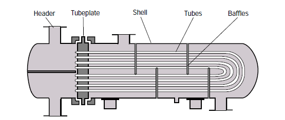
The larger, important parts of a shell & tube exchanger are listed below -
- Tubes: The tubes are the primary component of the heat exchanger, as they contain the fluid that is being heated or cooled. The tubes are typically made of a corrosion-resistant material such as stainless steel or copper.
- Tube sheets: The tube sheets are located at each end of the heat exchanger and hold the tubes in place. They are typically made of the same material as the tubes and are designed to withstand the high pressure and temperature of the fluids flowing through the tubes.
- Shell: The shell is the outer casing of the heat exchanger and surrounds the tubes. It is typically made of a strong, durable material such as carbon steel or stainless steel.
- Shell Cover: One of the main functions of the shell cover is to hold the tubes in place and support the weight of the tube bundle. The cover is typically made of the same material as the tubes and is designed to withstand the high pressure and temperature of the fluids flowing through the tubes.
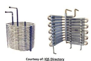
- Tube bundles: The tube bundles are the group of tubes that are held together by the tube sheets. They can be arranged in a variety of configurations, such as straight, U-shaped, or even spiral, depending on the specific needs of the application.
- Baffles: Baffles are used to direct the flow of the fluid over the tubes and ensure that it is evenly distributed. They are typically made of the same material as the shell and are mounted on the inside of the shell.
- Headers: The headers are located at each end of the heat exchanger and are used to distribute the fluid to and from the tubes. They are typically made of the same material as the shell and are designed to withstand the high pressure and temperature of the fluids.
- Nozzles: They are present on both shell and tube sides, to facilitate flow of the shell and tube side fluids between the heat exchanger and inlet / outlet piping
- Channels: The channels refer to the spaces between the tubes. These channels allow for the fluid that is flowing over the tubes (also known as the "shell side fluid") to come into contact with the tubes and transfer heat to or from the fluid flowing inside the tubes (also known as the "tube side fluid").
For a more detailed and complete list of shell & tube exchanger parts, refer to this article. It illustrates all the important parts in the construction of a shell & tube heat exchanger, as per the TEMA standards. It also gives you the exact correct nomenclature for each of those parts. For further details you can refer to the relevant TEMA guidelines.
Shell and tube heat exchanger types
There are two ways of classifying these exchangers -
A. based on the construction or structure of shell and tube sides
B. based on the service
Structure based classification of shell and tube exchangers
TEMA standards describe these various components in detail. A shell & tube heat exchanger (STHE) is divided into three parts:
- The front end
- Shell
- Rear end
Exchanger types based on the service
Process fluid which is to be either heated up or cooled down in the exchanger, is commonly referred to as the 'service'. The service may be single phase (either gas or liquid) or two-phase (mixture of gas and liquid).
On the other hand one of the fluids (shell or tube side) can be a non process fluid, which is only used for heating or cooling the process fluid. Such stream is known as a 'utility'. Utility can also be either single phase or two phase.
We may have two fluids in the shell and tube exchanger on both - shell side and tube side. That leads to multiple combination of services -
- single-phase (both shellside and tubeside)
- condensing (one side condensing and the other single-phase)
- vaporizing (one side vaporizing and the other side single-phase)
- condensing/vaporizing (one side condensing and the other side vaporizing)
Based on such combinations, we can have following types of exchangers -
- Heat exchanger: fluids on both sides are single phase process fluids
- Cooler: one stream is process fluid the other is a colder utility such as air or cooling water
- Heater: one stream a process fluid and the other a hot utility, such as steam or hot oil
- Condenser: on one side we have two phase flow of with gas at its dew point. This gas is condensed using a cold utility on the other side such air or cold water.
- Chiller: one stream a process fluid being condensed at sub-atmospheric temperatures and the other a boiling refrigerant or process stream.
- Reboiler: one stream a bottoms stream from a distillation column and the other a hot utility (steam or hot oil) or a process stream.
TEMA Guidelines
Design of a shell & tube exchanger is governed by standards provided by TEMA (Tubular Exchangers Manufacturers Association).
As per the TEMA standards, there are 3 important parts for shell & tube exchanger design.
- The front end
- Shell
- Rear end
Different configurations of these 3 parts result in different exchanger types as per TEMA. Following table from the TEMA standards explains the different possible configurations for each of the 3 broad parts.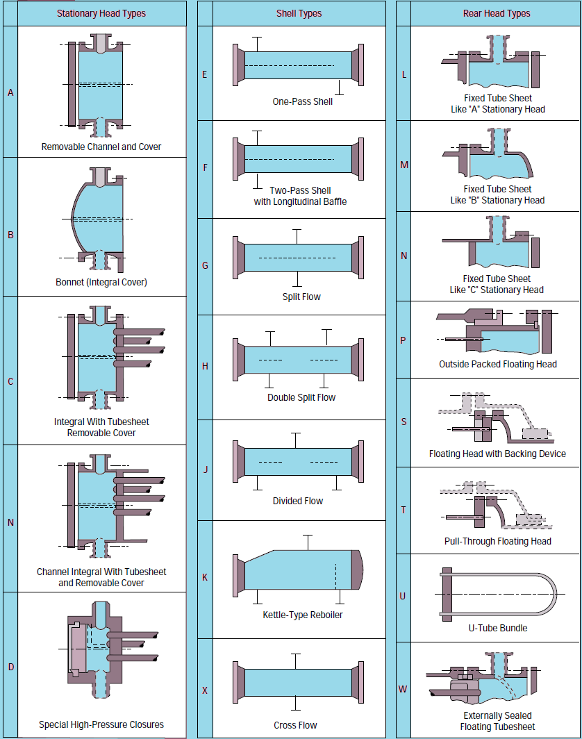
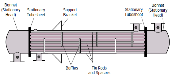
Other smaller parts are listed in this detailed diagram of a shell & tube heat exchanger, along with their correct nomenclature as per the TEMA standards.
Shell & Tube Heat Exchanger Types
Many different exchanger configurations can be easily created by different combinations of front end, shell and rear end. Moreover depending on how tube bundle is fixed to the front end or rear end cover, we have 3 broad types of shell & tube heat exchanger construction.
Fixed Tubesheet Exchanger
A fixed-tubesheet heat exchanger has straight tubes that are secured at both ends to tubesheets welded to the shell.
The main advantage of the fixed tubesheet exchanger is its low cost because of its simple construction. Fixed tubesheet being the least expensive shell & tube exchanger type, as long as we don't use any expansion joint.
But for the same reason, fixed tubesheet exchanger does not help much for services having large temperature difference between shell & tube sides. Because in such cases, an expansion joint would be needed.
Other advantages are that the tubes can be cleaned easily by removing the channel cover or bonnet. Moreover, absence of flanged joints helps to minimize the leakage of the shellside fluid.
But there is a disadvantage that the outsides of the tubes cannot be cleaned mechanically, as the tube bundle is fixed to the shell. Fixed tubesheet exchangers require that a clean fluid must be used on the shell side.
When you have a dirty fluid on tube side, you may consider this type of exchanger.
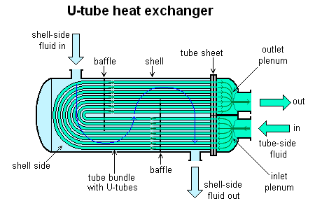
U tube exchanger
As the name suggests, in this type the tube bundle is U shaped. There is only one tube sheet. All the tubes start from upper half of this tubesheet, make a U turn in the shell and come back to the lower half of the same tube sheet. As shown in the following diagram.
The advantage of using a U tube bundle is that the tubes can freely expand as they are U turn end of the bundle is freely floating in the shell side. Hence a U tube exchanger is the preferred option where there is high temperature difference between shell & tube side fluids and tube expansion is expected.
But as the same time, this U shape of the tubes makes it difficult to mechanically clean them. Only chemical cleaning would be possible. Hence U tube exchangers are normally not preferred where we need to use a dirty or fouling service on the tube side.
These exchangers are also cost effective, as expansion joints are not needed and tube tube bundle is free to expand.
Floating head exchanger
In this type of shell & tube exchanger, one end of the tubes is kept fixed in a tubesheet attached to the shell side. While the other end is free to expand or 'floating' in the shell side. 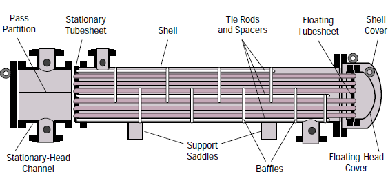
Thanks to this design, this type of shell & tube heat exchangers can withstand fluids to high temperature difference, as the tubes are free to expand. Also, the floating head cover can be easily removed to mechanically clean insides of the tubes. Therefore even dirty and fouling services can also be used on the tube side.
That makes this shell & tube heat exchanger type most versatile in terms of its applicability to different scenarios.
But the design is quite complex, making it also the most expensive type of shell & tube exchangers.
TEMA Type Nomenclature
Further, there are multiple types of shell, front end cover and rear end cover. The final heat exchanger configuration will depend on what we select.
For example, an AEL type shell & tube exchanger will consist of -
- Removable front end cover "A"
- One pass shell "E"
- Fixed tubesheet rear end cover "L" (like "A")
A, E and L are explained in the table from TEMA standards above.
Selecting a heat exchanger type
The structure of a shell and tube exchanger is decided based on a number of factors like -
-
- the nature of process fluids on both sides
- flow rates on both sides
- expected nature of operations and maintenance
- temperature difference on both sides and the required heat transfer area
Shell and tube heat exchanger fluid allocation
In a shell and tube heat exchanger, the fluid allocation refers to the allocation of the hot and cold fluids between the shell and the tubes. you will need to decide which should go through shellside and which will go through the tubes.
The choice of fluid allocation depends on several factors including the required heat transfer rate, the pressure drop across the heat exchanger, and equipment and maintenance cost. It's important to choose the appropriate fluid allocation for a given application to ensure efficient and reliable operation of the heat exchanger.
Generally, Fouling or corrosive fluids are typically placed on the tube side of a heat exchanger because they can cause damage to the shell side, which is typically made of less durable materials. Click the link to study more on shell and tube heat exchanger design procedure and fluid allocation.