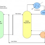
 Amine Treatment Unit - Amine treatment unit uses Methyl Di Ethanol Amine or MDEA to remove H2S and CO2 gases from other lighter hydrocarbon gases. An amine treatment unit involves two stages. First stage is an amine contactor where gases are bought in contact with amine and H2S and CO2 are absorbed in the liquid phase. Second stage is an amine regenerator where H2S and CO2 are stripped away from the liquid phase to regenerate the lean amine solution to be recirculated to the amine contactor column.
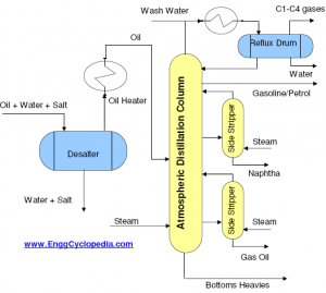 Atmospheric Distillation Unit- Crude oil is sent to the atmospheric distillation unit after desalting and heating. The purpose of atmospheric distillation is primary separation of various ‘cuts’ of hydrocarbons namely, fuel gases, LPG, naptha, kerosene, diesel and fuel oil. The heavy hydrocarbon residue left at the bottom of the atmospheric distillation column is sent to vacuum distillation column for further separation of hydrocarbons under reduced pressure.
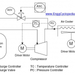 Centrifugal compressor systems - Typical centrifugal compressor system with a compressor, driver motor/turbine, compressor suction knock out drum, compressor aftercooler, antisurge valves etc.
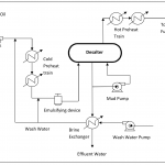 Crude Oil Desalting Unit - Crude oil introduced to refinery processing contains many undesirable impurities, such as sand, inorganic salts, drilling mud, polymer, corrosion byproduct, etc. The salt content in the crude oil varies depending on source of the crude oil. When a mixture from many crude oil sources is processed in refinery, the salt content can vary greatly.
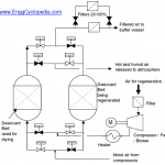 Instrument Air Dryer-Filter System - Typically instrument air drying systems consist of two parallel vessels with instrument air drying beds. When moist air is passed through such a dryer, moisture from the air gets absorbed by this bed and dry, dehumidified air is passed through the outlet. The dried air is filtered to remove any particulate matter, possibly entrained from the dryer bed.
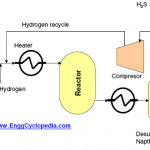 Naphtha Hydrotreating Unit - Heavy Naphtha cut from the atmospheric crude oil distillation column in a refinery is sent to a ‘Naphtha Hydrotreater Unit’. After the hydrotreater unit, naphtha is sent to an isomerisation unit or a catalytic reformer unit, which often use reforming catalysts. Most reforming catalysts contain platinum as the active material. Sulfur and nitrogen compounds present in naphtha cut from atmospheric distillation column can deactivate the catalyst and must be removed prior to catalytic reforming. Purpose of the hydrotreater unit is to remove before the naphtha cut goes to catalytic reformer.
![]() Block diagram for pygas processing - Pyrolosis gasoline or pygas (C5+ cut) is a liquid by-product derived from steam cracking of various hydrocarbon feedstocks in olefin plants. This C5+ cut, if left in its raw form, has little commercial value owing to its high reactivity and low stability. However, the stream contains many high-value components, such as isoprene, benzene, toluene and xylenes. Benzene is a key component in pygas. On a capacity basis, pygas extraction accounts for approximately 36% of global benzene.
Block diagram for pygas processing - Pyrolosis gasoline or pygas (C5+ cut) is a liquid by-product derived from steam cracking of various hydrocarbon feedstocks in olefin plants. This C5+ cut, if left in its raw form, has little commercial value owing to its high reactivity and low stability. However, the stream contains many high-value components, such as isoprene, benzene, toluene and xylenes. Benzene is a key component in pygas. On a capacity basis, pygas extraction accounts for approximately 36% of global benzene.
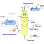 Sour Water Stripper Columns - In upstream crude oil production and processing facilities, the produced water from oil wells is separated in the slug catcher. Generally this produced water contains salts, hydrogen sulphide, carbon dioxide etc. Salts are removed using a desalting unit. Due to presence of acidic gases present in the produced water, sometimes it is called as sour water. For removal of these gases such as H2S, CO2 etc, the sour water is sent to sour water stripper columns.
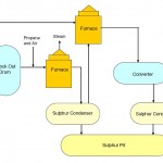 Sulphur Recovery Unit- The basic process used in SRU is ‘Claus Process’ which involves combustion of a part of H2S gas to form SO2. Later this SO2 is reacted (conversion) with H2S in presence of catalyst (Cobalt / molybdenum / aluminum oxide ) to form elemental sulphur and steam.
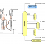 Residue Catalytic Cracking Unit - The main purpose of the Residue Catalytic Cracking process is to convert various reduced crudes to lower boiling, high value products, primarily C3-C4 LPG, gasoline, and light cycle oil. Using vapor phase chemical reactions in the presence of specialized FCC (Fluidized Catalytic Cracking) cracking catalyst, the long molecular chain FCC feedstock is cracked to shorter chain molecules.
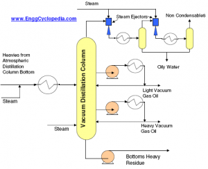 Vacuum Distillation Unit - Heavies from the atmospheric distillation column are heated to approximately 400˚C in a fired heater and fed to the vacuum distillation column where they are fractionated into light gas oil, heavy gas oil and vacuum reside. A typical process flow diagram (PFD) of such a vacuum distillation column is presented. Light vacuum gas Oil is sent to a hydrotreater and then to a ‘catalytic cracking’ unit to obtain smaller chain hydrocarbons. Heavy vacuum gas oil is also sent for cracking using hydrogen in a ‘hydrocracking unit’ to produce smaller chain hydrocarbons.
Add Comment