Piping and Instrumentation Diagrams (P&IDs) are a type of diagram used to illustrate the connectivity of various components in a control system, such as equipment, sensors, and valves. These diagrams use standardized symbols that represent different types of components, including actuators, sensors, and controllers. In this blog post, we will provide an overview of some of the most commonly used instrumentation P&ID symbols and their meanings.
By understanding these symbols, engineers, technicians, and other professionals can gain a better understanding of the system and how it functions. Note that they may differ slightly from one project to another.
Table of content:
Instrumentation lines symbols
Sensing Devices and Detectors
Indicators and Recorders
Controllers
Instrumentation lines symbols
In Piping and Instrumentation Diagrams (P&IDs), line symbols are used to represent different types of pipelines, such as process lines, utility lines, and instrumentation lines. These symbols indicate the flow direction, size, and material of the pipeline.
Process Connection

Process connection lines are represented by a solid line that shows the direction of flow.
Electric signal

An electrical signal line is a type of instrumentation line that represents the transmission of electrical signals between devices or components in a process system. These lines are used to indicate the flow of signals that carry information related to the control, measurement, or monitoring of the process.
Electric binary signal

An electric binary signal line is used to represent the transmission of digital signals between components in a process system. These signals are typically used to indicate the state of a device or component, such as an on/off switch or a limit switch.
Capillary connection

In the P&ID diagram, capillary connection lines are used to represent the connection between a pressure gauge and its associated diaphragm or Bourdon tube.
Software signal

A software signal line is used to represent the flow of digital signals between software-based components in a process system. By using these lines, engineers and technicians can better understand the flow of data within the process.
Mechanical link

A mechanical link is used to represent the transmission of mechanical power or motion between components in a process system.
Hydraulic signal

These lines are used to represent the transmission of fluid pressure between components in a process.
Pneumatic signal

Pneumatic binary signal

In a P&ID diagram, pneumatic signal and pneumatic binary signal lines are used to represent the transmission of air pressure between components.
Waveguide
A waveguide is a structure that is designed to carry electromagnetic waves, such as radio waves, microwaves, and light waves.
Radio link
![]()
A radio link signal line represents the transmission of electromagnetic waves between components in a process system using radio frequency (RF) technology.
Sonic wave

A sonic wave signal line represents the transmission of sound waves between components in a process system. Sonic waves are a type of mechanical wave that travels through a medium, such as air or water, and can be used for various purposes in process control and measurement
Sensing Devices and Detectors
Sensing devices and detectors are used in process systems to measure and monitor various parameters, such as pressure, temperature, flow rate, level, composition, and the presence of particular substances, such as gases or radiation. In a P&ID Diagram, sensing devices and detectors are represented by specific symbols that indicate their type and function in a process system.
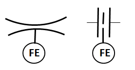
Orifice meter

An orifice meter is a flow measuring device which measures flow rate using pressure difference by decreasing the flow area. It consists orifice plate with a hole in it to decrease the pressure of the fluid. The above given P&ID symbol of the orifice meter shows how the orifice plate is a plate in between the flowing fluid.
Venturi meter
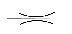
It works on a similar principle as the orifice meter. The only difference is that area reduces gradually in the venturi meter. The P&ID symbol of the venturi meter represents a gradual reduction in area.
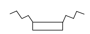
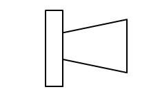
Rotameter
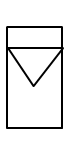
Rotameter is a variable area type flow measuring device. The inverted triangle in P&ID shows the rotor inside the rotameter.
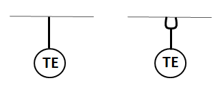
Pitot tube
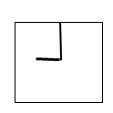
A Pitot tube is a device used to measure point velocity by using stagnation pressure. The end of the horizontal line in the P&ID symbol of the pitot tube represents the impact or stagnation point of the fluid flow.
Thermocouple
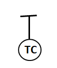
A thermocouple is a commonly used temperature sensor in process systems that measures temperature based on the principle of the seeback effect.
Flow element
To represent a general flow measuring device in P&ID, flow elements are used.
Temperature element
To represent the general temperature measuring device in P&ID, temperature elements are used.
Differential pressure cell

A differential pressure cell is a device that measures the differential pressure between two inputs.
Conductivity cell
A conductivity cell is a sensing device that measures the electrical conductivity of a fluid.
Radiation detector
A radiation detector is a sensing device that is used to detect and measure ionizing radiation.
Indicators and Recorders
Indicators and recorders are devices used in process control systems to display and record process variables such as temperature, pressure, level, and flow rate. Indicators and recorders are important components of process control systems that convert the electrical or mechanical signals generated by sensors or other instruments into a readable and understandable format for operators or control systems. In other words, they take the raw signals from the instrument loop and transform them into a form that can be easily interpreted and used to monitor and control process variables such as temperature, pressure, level, and flow rate.
Locally mounted flow indicator
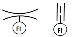
A locally mounted flow indicator is a type of flow meter that is installed directly in the process line and provides a visual indication of the flow rate of fluid or gas in the pipeline.
Board-mounted flow indicator
A board-mounted flow indicator is a type of flow meter that is mounted on a circuit board or other electronic device for use in monitoring and controlling fluid or gas flow.
Locally mounted Temperature or Pressure indicator
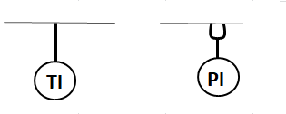
A locally mounted temperature indicator is a type of temperature measuring device that is installed directly in the process line and provides a visual indication of the temperature of fluid or gas in the pipeline.
A locally mounted pressure indicator is installed directly in the process line and gives a visual indication of pressure.
Board-mounted pressure indicator

A board-mounted pressure indicator is typically designed to be integrated into a larger system or device and may be used to monitor and control pressure in industrial processes.
Pressure recorder

A pressure recorder is a type of instrument used to record the pressure of a gas or liquid over time. It typically consists of a pressure sensing element, a mechanism for recording the pressure readings, and a power source or means of storing the data.
Temperature recorder
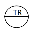
A temperature recorder is a type of instrument used to record the temperature of a given environment over time. It typically consists of a temperature-sensing element and a mechanism for recording the temperature readings.
Controllers
Controllers are electronic devices that receive and process signals from sensors or other instruments in a control system. They then use this information to manipulate or adjust the operation of other components within the system. They play a critical role in maintaining precise and stable conditions, such as temperature, pressure, and flow rate. By processing signals from sensors and adjusting the position or operation of other system components, controllers can help ensure that these conditions are maintained within a desired range.
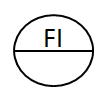
Flow controller

A flow controller is a type of controller that regulates the flow rate of a fluid through a system. It does this by adjusting the position of a valve, which in turn controls the size of the opening through which the fluid can flow.
Level controller

A level controller is used to regulate the level of a liquid within a tank or vessel. It receives signals from sensors that measure the liquid level and uses this information to determine the appropriate valve or pump position to maintain the desired level.
Pressure controller

A pressure controller is used to regulate the pressure of a fluid within a system.
Temperature controller

A temperature controller regulates the temperature of a system by adjusting a heating or cooling device.
Proportional controller

It is a simple type of controller that provides a proportional response to changes in the process variable. It is a type of feedback control system that adjusts the output based on the difference between the desired setpoint and the measured process variable.
Proportional Integral controller

PI controller provides an immediate response to changes in the process variable and accumulates the error over time and adjusts the output to eliminate any steady-state error.
Proportional Integral Derivative controller

PID controller predicts the future behavior of the process variable and adjusts the output to counteract any anticipated changes. PID controllers are highly effective at regulating complex process variables that can change rapidly or unpredictably.
Current to pneumatic

Current to pneumatic (I/P) converters are devices that convert an electrical signal into a proportional pneumatic output.