As a process engineer, it is very important to understand the storage tanks' P&ID arrangement. Because storage tanks play a crucial role in various industrial processes, as they are used to store and hold materials such as liquids, gases, and other substances.
Storage tanks of various kinds are used to store process fluids of various types, under different process conditions. But the basic arrangement remains roughly the same for different types of storage tanks.
Table of content:
Storage tank P&ID arrangement
Guidelines to create a P&ID for storage tanks
Storage tank P&ID arrangement

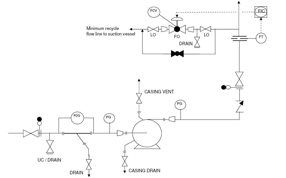
The figure above represents a typical P&ID for storage tanks.
Guidelines to create a P&ID for storage tanks
Selection of tank symbol
The proper tank symbol should be selected first of all, as shown in the presented drawing. This should be selected from the list of equipment symbols on the legend sheets of a particular project.
The selection of a tank symbol in a P&ID arrangement should be based on a thorough understanding of the specific tank being represented, the material of construction, the shape of the tank, and any applicable standards and conventions.
Tank internals
Tank internals should then be indicated as per proper symbols on the legend sheets. These internals can be inlet pipe, vortex breaker on the outlet lines, manway, etc.
A vortex breaker is a device installed inside a storage tank to prevent the formation of a vortex in the liquid as it drains out of the tank. The vortex breaker symbol should be placed near the bottom of the storage tank, adjacent to the outlet or drain pipe.
Normally for large enough tanks, a manway has to be provided as indicated in the sample drawing for maintenance access.
Nozzles
All the nozzles on the storage tank should then be correctly represented with size and flanges. This includes inlet and outlet nozzles, overflow line, minimum recirculation line, blanketing gas line, PSV connection, and instrument nozzles, as shown in the sample drawing presented here.
Inlet / Outlet lines
Inlet and outlet lines are the next to be drawn up. These lines are used to introduce or remove material from the tank and connect the tank to other components or systems.
The inlet line will typically be shown entering the tank at the top or side, while the outlet line will typically exit the tank at the bottom. Line number, material class, size, etc. is to be correctly assigned to each of the lines.
Instrumentation
Typical instrumentation on the tank would be level gauges and transmitters plus pressure gauge and transmitters. For the tank under continuous operation a level control valve has to be provided as indicated in the sample drawing. For a tank with blanketing gas, a self regulating pressure valve has to be provided on the blanketing gas inlet line. Normally alarms/trips are provided for High Pressure, High Level, Low Pressure, and Low Level.
Isolation valves, spectacle blinds, spacers
In a P&ID arrangement of a storage tank, isolation valves, spectacle blinds, and spacers are often included to help control the flow of material and isolate the tank from the rest of the system. Isolation valves are typically used to shut off the flow of material in the inlet or outlet lines, or to isolate the tank from other components or systems. Spectacle blinds are used to block the flow of material in a pipeline or to isolate a section of the pipeline. Spacers are used to separate sections of a pipeline, to provide space for maintenance, or to isolate different materials.
Isolation valves, spectacle blinds, spacers, etc. to be used for maintenance, and should be drawn up on the inlet/outlet lines. The spectacle blinds, spacers, etc. can be connected right next to the isolation valves and equipment nozzles, as indicated in the sample drawing presented here.
Vents & Drains
Drains are typically used to remove any material or liquids that have accumulated in the tank. Drains should be provided on the tank bottom and on the bottom outlet lines for the complete draining of the tank and associated piping for maintenance purpose.
A vent has to be provided on top of the tank for complete venting of the tank for maintenance purpose. In some cases, the tank may be open to the atmosphere through a vent during normal operation. In such cases, a bird screen has to be provided on the vent line.
Utility connection
For purging the tank with nitrogen or steam, a utility connection can be provided directly on the storage tank.
All the guidelines given here are very general and may be modified as per specific requirements of any particular project.