Gas-liquid separators are important devices used in various industries to separate gas and liquid components from a mixed stream. The design of a gas-liquid separator involves various parameters such as the flow rate, pressure, temperature, and composition of the gas and liquid phases. We will explore the design calculations involved using sample problem.
Table of content:
Gas liquid separator
Gas liquid separator sizing calculation
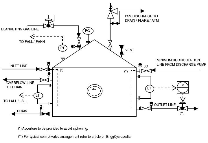
Gas liquid separator
A gas-liquid separator is a device that separates gas and liquid components from a mixed gas-liquid stream. The separation is based on the differences in the physical properties of the gas and liquid phases, such as their densities, viscosities, and surface tensions. The separation process involves a combination of gravity, centrifugal force, and other mechanical or electrical forces to separate the gas and liquid phases.
The main purpose of a gas-liquid separator is to remove liquid droplets from the gas stream to protect downstream equipment such as compressors, turbines, and pipelines. Liquid droplets in the gas stream can cause corrosion, erosion, and other types of damage to the equipment, as well as reduce the efficiency and performance of the equipment.
Gas liquid separator sizing calculation
Problem Statement
Perform separator sizing calculations for a vertical gas-liquid separator used for separation of fuel gas bubbles entrained in water flow.
Flow rate of water = 18 m3/hr
Entrained Flow of fuel gas = 100 m3/hr
Operating temperature of separator = 25 0C
Operating pressure of separator = 0.2 barg (near atmospheric)
Separation efficiency required is to remove 80% of gas bubbles above the size of 10 microns.
Fuel gas properties can be approximately taken as properties of ethane.
Size the drum as,
(i) an empty vessel and
(ii) vessel with demister pad with K=0.1 m/s for removing 100 micron droplet size.
Compare the minimum vessel size requirements in both the cases.
Solution
For the case
(i) Separator sizing of two phase separator as an empty vessel is performed in EnggCyclopedia's solved sample problem. This type of separator relies only on gravity settling of liquid droplets and requires sufficient residence time for the gas phase so that the liquid droplets can settle down. This often results in a large vessel for separation of small liquid droplets.
(ii) A demister pad assists the separation of liquid droplets by impinging liquid droplets into each other to from bigger drops which are too heavy to rise with the gas and drop down into the pool of liquid in the separator.
For gas liquid separators, following equation for the gas phase design velocity governs the separator diameter,

ρL and ρG are the densities of liquid and gas phase respectively.
K is a proportionality constant which depends on a number of factors which include liquid viscosity, surface tension, entrainment loading, and the content of dissolved and suspended solids. For our sample problem, we know the 'K' value to be 0.1 m/s for removing 100 micron size liquid droplets.
It shoud be noted that the 'K' value is directly proportional to the square of the droplet size to be knocked out from gas. Hence for 10 micron size particles, 'K' calue is estimated as,
K = 0.1×(10/100)2 = 10-3 Thus the separator sizing can be performed in following basic steps.
Step1: Determination of important properties of water and fuel gas.
Water density at 25 0C = 994.72 kg/m3
Water viscosity at 25 0C = 0.9 cP
For fuel gas properties,
Molecular weight of ethane = 30 gm/gmole
Fuel gas density at 25 0C = 1.45 kg/m3
Fuel gas viscosity at 25 0C = 0.0069 cP
Step2: Calculation of design velocity.
The design velocity for gas phase is calculated as follows,
with K = 10-3, ρL = 994.72 kg/m3 and ρG = 1.45 kg/m3
Vt = 10-3 × √((994.72 - 1.45)/1.45) = 2.6×10⁻² m/s
Step3: Calculation of drum diameter.
This design velocity for gas phase is related to the drum diameter as,
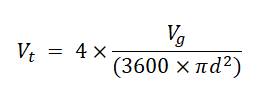
where, Vg is gas volumetric flow (m3/hr) and 'd' is vessel diameter
Hence,
d = √Vg/(900×π×Vt)
d = √100/(900×π×2.6×10-2) = 1.166 m
Step4: Comparison of drum diameter for both cases and calculation of length of drum.
Compared to minimum drum diameter requirement of 2.13 m for empty vertical KO Drum which only relies on gravity settling for separation of liquid droplets. It can be readily observed that drum size is reduced by 15% in terms of drum diameter by using a demister pad.
Using the L/D ratio of 3.5 ,
L = 3.5 × 1.17 = 4.095 m
This length has to be checked to be compliant with project specification of liquid residence time between HLL (High liquid level) and LLL (Low liquid level). If the length is not sufficient to provide enough residence time between HLL and LLL, then the length can be increased along with the diameter by resepcting the L/D ratio constraints.