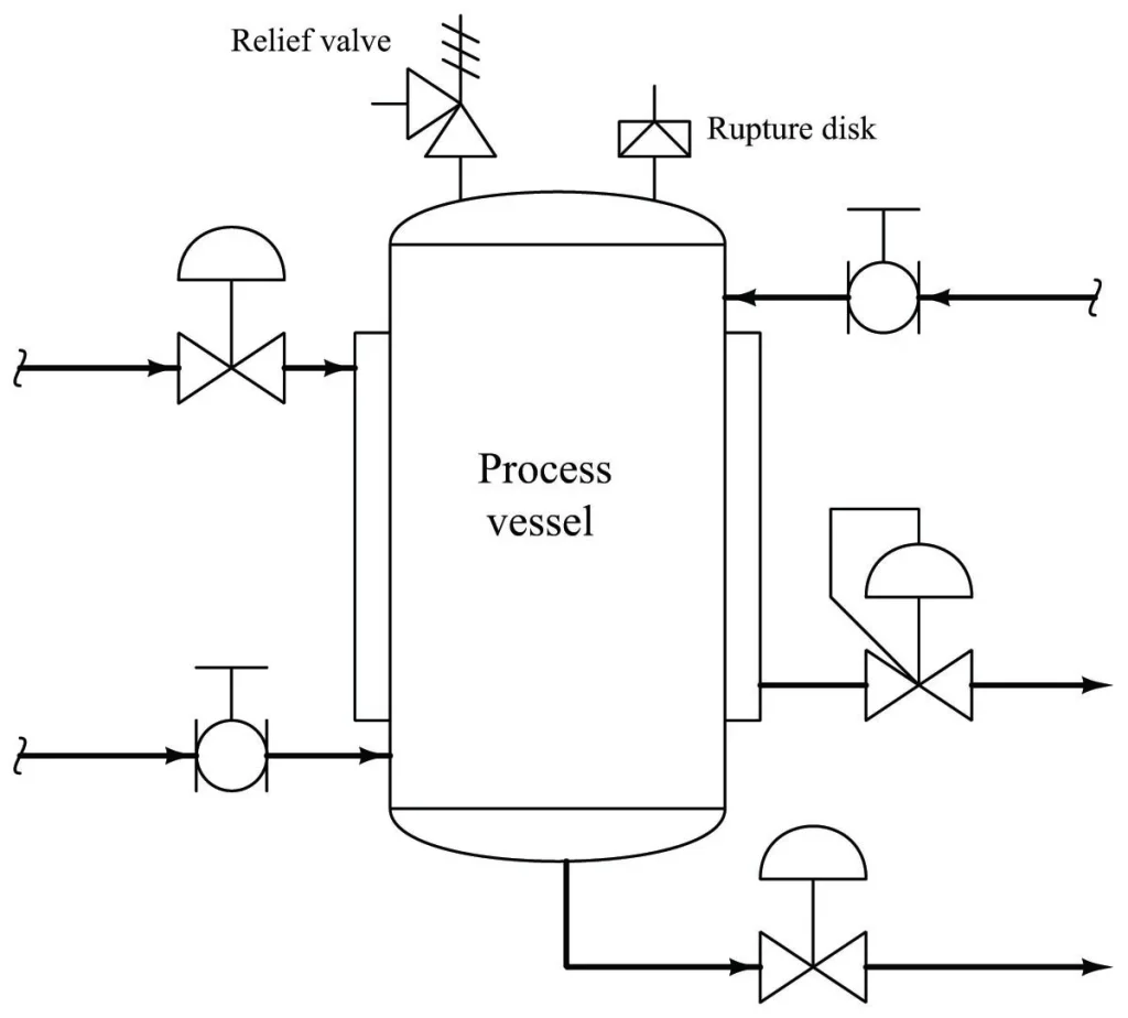
A blocked liquid discharge is an overpressure scenario where a valve on the outlet of equipment is closed, resulting in the accumulation of fluid and pressure build-up. The pressure can reach the design pressure of upstream pumps or compressors combined with the height of the liquid column upstream
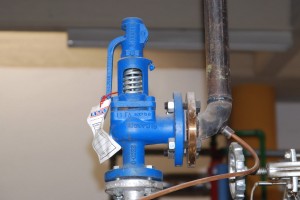
In the case of a blocked liquid discharge scenario, pressure can build up inside the equipment, which can lead to overpressure and potential damage. A pressure relief valve (PRV) can be used to mitigate this risk by automatically relieving excess pressure when it reaches a predetermined set point.
Table of content:
Overpressure due to blocked liquid discharge
Pressure relief valve sizing calculation for blocked liquid discharge
PSV sizing calculator – blocked liquid discharge
Overpressure due to blocked liquid discharge
Blocked liquid discharge is an overpressure scenario where a valve on the equipment outlet, such as a vessel or heat exchanger, is closed. Despite the valve being closed, fluid continues to flow into the equipment, leading to the accumulation of fluid and an increase in pressure.
If there is no outlet for this fluid, the pressure build-up can reach the design pressure of the upstream pumps or compressors combined with the height of the liquid column upstream. The pressure build-up can be dangerous and may cause equipment failure or even a catastrophic accident.
Therefore, it is important to consider the normal inlet flow as the minimum relieving flowrate in this scenario. This means that a pressure relief valve should be installed and designed to handle the minimum relieving flowrate to ensure the safety of the equipment and prevent overpressure incidents.
Check this post to study more about various overpressure scenarios which are considered for pressure relief valve sizing.
Pressure relief valve sizing calculation for blocked liquid discharge
Problem Statement
Design a pressure relief valve for the following service.
Protected equipment : Separator vessel
Relief service : Water
Reason for relief : Blocked liquid discharge
Relieving Rate : 100,000 kg/hr
Water Density : 1000 kg/m3
Water Viscosity : 0.8 cP
Set pressure : 5 barg
Accumulation : 10%
Back pressure at relief valve discharge : 0.5 barg
Type of relief valve : Conventional
Solution
This sample problem for relief valve sizing calculation can be solved in following steps, which are based on pressure relief valve sizing procedures described in API RP 520 Part I.
Step1
As per API RP 520 Part I, the required orifice area for relief valve discharge is calculated using the following equation,
......1
A : orifice are requirement in mm2
Q : flowrate in lit/min
Q = 100000×1000/(1000×60) = 1666.67 lit/min
G : Specific gravity of the liquid = 1 (for water)
P1 : upstream pressure in kPag
P1 = 500 kPag
P2 : downstream pressure in kPag
P2 = 50 kPag
Kd : Coefficient of discharge
Kd = 0.65 for liquid service
KW : correction factor
KW = 1 (for conventional relief valves with near atmospheric backpressure)
KC : combination correction factor for use of rupture discs
KC = 1 (for absence of rupture disc upstream to the valve)
Kν : correction factor due to viscosity
Kν = 1 (calculated using following equations from API 520 Part I)

and,

Plugging this data into equation (1), the minimum required orifice area for the relief valve is calculated to be,
A = 14.17 cm2
Step2
The next higher available orifice area should be selected for the pressure relief valve to be actually installed. Referring to the table of standard orifice sizes given in EnggCyclopedia's relief valve sizing calculator,
Next high available orifice area is selected to be A = 18.49 cm2 and the corresponding designating letter is 'L'. Available valve sizes are '3L4' and '4L6', which correspond to different nozzle sizes for suction and discharge nozzles of the pressure relief valves. For a '3L4' valve suction nozzle is of 3" size and discharge nozzle of 4" size. Similarly for a '4L6' valve suction nozzle is 4" and discharge is of 6" size.
PSV sizing calculator – blocked liquid discharge
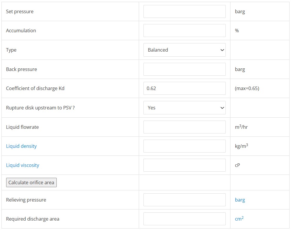
Check the pressure safety valve sizing calculator for blocked outlet of a liquid filled vessel. The post also contains table which represents the standard orifices with their designating letters and corresponding area.
