Pressure relief valves are critical components in many industrial processes. Critical gas flow refers to the flow of gas at pressures and temperatures above their critical points, where the gas becomes a supercritical fluid with properties of both a gas and a liquid. In such scenarios, overpressure situations can lead to equipment failure, leaks, and potentially catastrophic accidents. Pressure relief valves are installed to prevent such situations. Proper sizing of pressure relief valves is crucial for their effective operation in critical gas flow systems.
Table of content:
Critical gas flow service
Pressure relief valve sizing calculation for critical gas flow
Critical gas flow service
Critical gas flow refers to the flow of gas at pressures and temperatures above their critical points, where the gas can no longer be compressed and becomes a supercritical fluid with properties of both a gas and a liquid.
In such scenarios, overpressure situations can occur if the pressure in the system exceeds the design pressure of the equipment, which can result in equipment failure, leaks, and potentially catastrophic accidents. Pressure relief valves play a critical role in preventing such situations by automatically relieving excess pressure when the pressure inside the system reaches a predetermined setpoint.
However, in critical gas flow scenarios, selecting the appropriate pressure relief valve can be more challenging. This is because the properties of supercritical fluids can differ significantly from those of gases or liquids, making accurate predictions of valve performance more difficult. For example, the flow rate and capacity of the valve may be affected by the compressibility of the supercritical fluid, which can make it more difficult to accurately determine the required valve size.
To address these challenges, it is important to carefully consider the properties of the supercritical fluid and the operating conditions when selecting and sizing pressure relief valves for critical gas flow scenarios. Additionally, it may be necessary to conduct testing or simulations to ensure the valve will perform as expected in such conditions.
Pressure relief valve sizing calculation for critical gas flow
Problem Statement
Design a pressure relief valve for the following service.
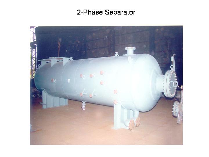
Protected equipment : Separator vessel
Relief service : Fuel Gas
Reason for relief : Blocked gas discharge
Relieving Rate : 10,000 kg/hr
Gas Density : 4.1 kg/m3
Ratio of specific heats for the gas (CP/CV) : 1.35
Compressibility factor of gas = 0.95
Relieving temperature = 200C
Set pressure : 5 barg
Accumulation : 10%
Back pressure at relief valve discharge : 0.5 barg
Type of relief valve : Conventional
Solution
This sample problem for relief valve sizing calculation can be solved in following steps, which are based on pressure relief valve sizing procedures described in API RP 520 Part I. The first step is to determine whether the gas flow type is critical or sub-critical.
Step1
The first step is to determine if the flow conditions are critical. For this purpose the critical flow pressure (Pcf) downstream to the relief valve has to be calculated using the following equation from API RP 520 Part I,
P1 : Relieving pressure upstream to relief valve in bara
P1 = 6.51 bara (including 10% accumulation)
k : Ratio of specific heats of the gas .. (CP/CV)
k = 1.35
Pcf : Critical flow pressure for the given flow conditions in bara
Pcf = 3.5 bara
If the pressure downstream or back pressure of the relief valve is lower than the critical flow pressure, then the flow is said to be of critical type. In this case, the actual pressure downstream to the relief valve cannot fall below the critical flow pressure even if much lower pressure exists further downstream to the valve. Mass flow relieved cannot increase any further, for the given set of flow conditions upstream to the valve.
In the present case, back pressure (1.5 bara) < Pcf (3.5 bara). Hence the flow is of critical type.
Step2
Next step is to use the relief valve sizing procedure given in the API 520 part I for critical flow type gas relief valve. The following equation is used,

... (1)
A : orifice are requirement in mm2
W : flowrate in kg/hr
W = 10,000 kg/hr
T : Temperature in Kelvin
T = 273.16 + 20 = 293.26 K
Z : compressibility factor of gas
Z = 0.95
C : coefficient for fire case as a function of k (CP/CV) as per following equation,

Here, C = 351.6
P1 : Relieving pressure upstream to relief valve in bara
P1 = 6.51 bara (including 10% accumulation)
Kd : Coefficient of discharge
Kd = 0.975 for gas service
Kb : capacity correction factor due to back pressure
Kb = 1 (for conventional relief valves with near atmospheric backpressure)
KC : combination correction factor for use of rupture discs
KC = 1 (for absence of rupture disc upstream to the valve)
Plugging this data into equation (1), the minimum required orifice area for the relief valve is calculated to be,
A = 22.0 cm2
Step3
The next higher available orifice area should be selected for the pressure relief valve to be actually installed. Referring to the table of standard orifice sizes given in EnggCyclopedia's relief valve sizing calculator,
Next high available orifice area is selected to be A = 23.20 cm2 and the corresponding designating letter is 'M'. Available valve size is '4M6', which correspond to different nozzle sizes for suction and discharge nozzles of the pressure relief valve. For a '4M6' valve suction nozzle is of 4" size and discharge nozzle of 6" size.