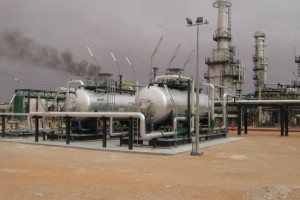
One of the most common control element in the process control industry is the control valve. A control valve helps regulate the flow of a fluid (gas, steam, water, or chemical substance) in order to keep the regulated process variables (pressure and flowrate) as close as possible to the desirable set point. Control valves can generally be designed to handle all types of fluids at temperatures from the cryogenic range up to 500+ degrees Celsius steam temperatures.
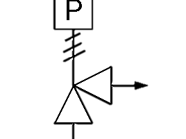
Control valves are typically operated with instrument air and are therefore characterized as pneumatically actuated valves. Electric and electro-hydraulic actuators can also be used with control valves. However, they are generally more complicated and thus more expensive compared with pneumatic actuators. They offer advantages where no instrument air or instrument gas supply source is available, in low ambient temperatures in which condensed water in pneumatic supply lines could freeze, or where unusually large driving (stem) forces are necessary for valve movement. Pneumatic type control valves are typically globe valves.
Control valves are typically designed to operate in a closed loop, i.e. information regarding the process variable is continuously fed back to the controller set point in order to provide continuous, automatic corrections to the process variable. This is usually referred to as the feedback loop.
In order to be able to order the best control valve suited for the application, the user has to provide the valve manufacturer with all the necessary information to select and design a suitable control valve.
- Type of fluid through the valve
- Process properties of the fluid (viscosity, vapor pressure etc.), in order to be able to inform about any special-design conditions, like for example possibility for flashing etc.
- Normal, maximum and minimum flowrate values through the control valve need to be specified, in order to be able to calculate the design flow coefficient Kv/Cv of the valve and the valve's capacity, i.e. the flow rate through the valve under steady conditions. The flow coefficient, Cv,expressed in m3/h, is the flow rate that flows through the valve resulting to a static pressure drop of 1 bar across the valve. Knowing fluid details at various operating points and taking into consideration the valve specific construction details (cage etc), it is possible to calculate a Cv value for each one of these operating conditions. The selected Cv value of the valve must be greater than the Cv value at the worst operating condition.Knowing maximum and minimum flow rate also enable us to calculate the valve's turndown ratio, i.e. the maximum controllable ratio of maximum / minimum flow and we are also able to calculate other operating characteristics like shut-off DP pressure and maximum actuating force, thereby allowing us to select the most suitable actuator.
- Normal operating, maximum and minimum pressure at valve inlet and outlet.
- Pressure drop during normal flow and shutoff conditions.
- Installation (indoors / outdoors)
- Maximum allowable noise level
- Construction materials, type of end connections
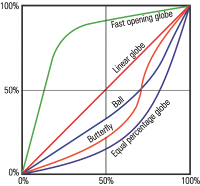
- Information about trim characteristic, i.e. whether the valve will be of linear characteristic (flow capacity increases linearly with valve travel), equal percentage characteristic (flow capacity increases exponentially with valve trim travel) or quick opening characteristic (large changes in flow can be achieved for very small changes in valve trim travel).
- Action desired on air failure: valve to open (FAIL OPEN), close (FAIL CLOSE), or retain last controlled position (FAIL LAST POSITION)
- Instrument air supply available, operating and design pressure values for the instrument air supply.
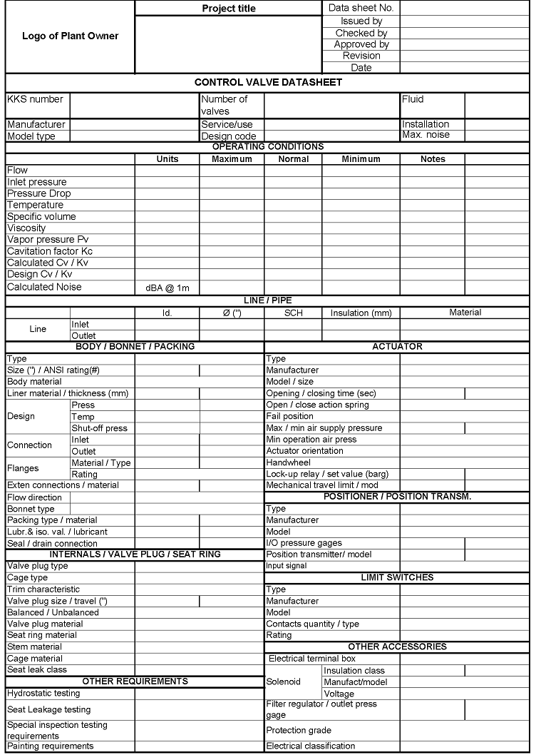
Figure 3 - Typical pneumatic-type control valve datasheet