Many of the automated instruments in process industry are often operated using instrument air or pneumatic signals. The instrument air is generally required to be available at 7-8 bar pressure. Within the instrument air supply system, atmospheric air supply is filtered, compressed, dried and cooled to be used for instrument signals.
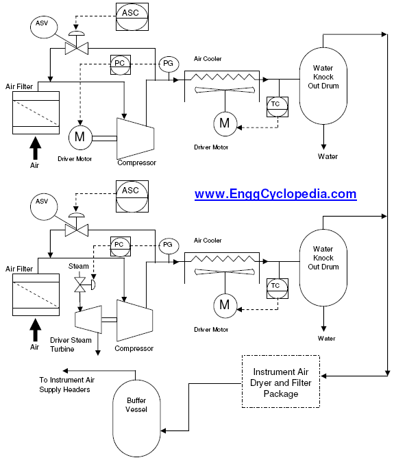
Figure 1 - Typical PFD for an Instrument Air Supply System
Figure-1 depicts a typical process flow diagram (PFD) for instrument air supply system. As shown in figure-1, instrument air supply system is typically comprised of filters, compressors, knock out drums, aftercoolers, intercoolers and air drying (dehumidifying) packages.
Air used for instrument air systems is taken from the atmospheric air supply and compressed to required pressure. Any particulate matter is unacceptable in the compressor, since it can cause damage. Hence the air is filtered before sending to compressors. Also, care has to be taken to place the air intake point out of any hazardous areas to keep hydrocarbons from entering the instrument air system.
Instrument air supply compressors are typically two or more in numbers. It is a good engineering practice to use different drivers (electric motor, steam turbine, diesel engine etc.) to drive these different compressors. So that in case of failure of one utility system (electricity for example), instrument air system can still be maintained operational by running a compressor using the other utility (steam for example).
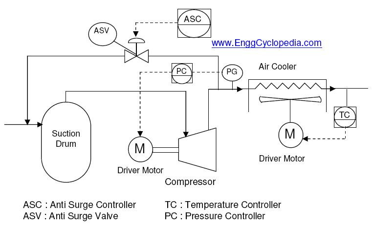
As discussed for typical centrifugal compressor process flow diagram (PFD), these compressors are generally accompanied by aftercoolers to maintain the compressor discharge temperature.
The atmospheric air being compressed is generally humid. At high pressure at compressor outlet, the moisture content in the air tends to condense. The instrument air is required to be dry to a certain extent hence water droplets being formed after cooling the air from compressor outlet are removed using a Knock Out Drums (KOD), which is a two phase separator with demister pads and wire mesh.
Further drying of the compressed air can be carried out by sending the compressed air stream to an ‘instrument air dryer/filter package’. A dryer and filter package generally uses two desiccant beds (2X100%) in parallel. At a given time one desiccant bed absorbs the moisture from moist compressed air and sends the dried air to instrument air system. The other bed is regenerated at this time by circulation of hot air to free the absorbed moisture. After regeneration phase, this bed remains on standby and is used for drying when the first bed becomes saturated with moisture.
Dried, cooled and compressed air is then sent to instrument air supply headers. There headers need to be equipped with low pressure alarm and low low pressure trip over the instrument air system. Usually, such a trip triggers shutdown of the whole production.
