In upstream crude oil production and processing facilities, the produced water from oil wells is separated in the slug catcher. Generally this produced water contains salts, hydrogen sulphide, carbon dioxide etc. Salts are removed using a desalting unit. Due to presence of acidic gases present in the produced water, sometimes it is called as sour water. For removal of these gases such as H2S, CO2 etc, the sour water is sent to sour water stripper columns.
Even in crude oil refining facilities, steam and water are often used in many units such as atmospheric distillation unit, naphtha hydrotreater unit, kerosene hydrotreater etc. These units produce sour water as a result of steam/ water coming in contact with sulphur products in the hydrocarbons. This sour water is also then sent to sour water stripper columns for H2S removal. The H2S removed is sent to sulphur recovery unit to produces liquid sulphur.
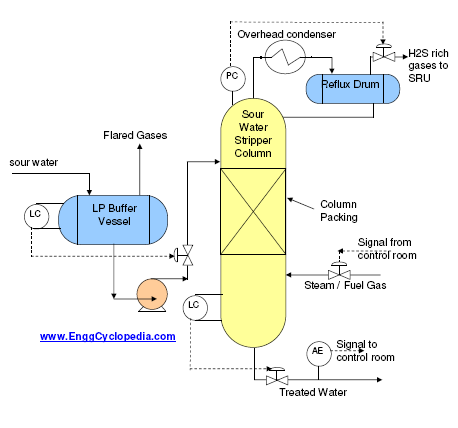
Figure 1 - Typical PFD for a sour water stripper column
Typical process flow in a sour water stripping unit
Typically a sour water flow in crude oil processing facility or in a refinery is not steady. Sour water is gathered from a number of different sources and treated in a single column. For upstream oil production and storage facilities, the produced water comes along with crude oil in a pipeline. During pigging of these pipelines vast quantities of sour water are produced in the slug catcher, which may far exceed the sour water stripper flow handling capacity. Hence a buffer vessel is generally provided upstream to the stripper column to accommodate extra sour water quantities in case of a peak e.g. pigging.
Sour water from buffer vessel is sent to the sour water stripper column under level control. In case the flow to the column sees major fluctuations which may frequently disturb the column operation, flow control valve on the column inlet water line can be used with a cascading signal from buffer vessel level control. Gases flashed in the buffer vessel can be flared or sent to the sulphur recovery unit, if they are rich in H2S.
The stripper column may use either steam or fuel gas to strip off the H2S dissolved in water. Water is introduced from top of the packing or trays section and steam/fuel gas flows upwards from the bottom of the trays/packing section as shown in the typical PFD in figure-1. Contact between water and vapor phase allows transfer of H2S from water to the gas phase (steam or fuel gas). Gases rich in H2S are removed from the top of the column and treated water is taken out from the bottom of the column, under level control for the liquid level of the bottom section of stripper column.
If steam is used in the stripper column for removing H2S, then overhead condenser and reflux drum are required at the top outlet of the column as shown in typical PFD in figure-1. The vapor outlet line of the stripper column is also equipped with a pressure control valve to maintain the sour water stripper column overhead pressure. Steam used can be either taken directly from the utility steam and sent to column or the treated water from bottom of the column can be sent to a reboiler to produce steam which is circulated back to the column for H2S removal.
If fuel gas is used instead of steam to remove H2S, reboilers, condensers, reflux drums etc. are not required. But the gases from column overhead outlet have a high hydrocarbon content.
An analyzer is installed to detect the H2S content in the sour water stripper outlet. This analyzer generally transmits signal to the control room and steam/fuel gas flow can be adjusted from the control room in order keep the H2S content in treated water well below the allowable H2S content limit. Alternatively, a controller can be used to directly throttle the steam/fuel gas flow based on a setpoint of H2S content in the treated water.
