The transfer of heat from and to fluids is an important part of chemical processes. Heat exchanger equipment is used for such processes. A heat exchanger is a device that transfers heat / thermal energy from one fluid to another. It is very important to understand the heat exchanger design procedure.
Table of content
1. Heat Exchanger Equations & Sizing Calculations
2. Design Procedure
3. Heat Exchanger Design Software
Heat Exchanger Equations & Sizing Calculations
The design of a heat exchanger involves specifying several factors, including the type of fluids being used, the flow rates of the fluids, the desired heat transfer rate, and the required pressure drop. A suitable heat exchanger must be selected to meet desired heat transfer rate and the minimal pressure drop for the specific application.
The major objective during the design of the exchanger is to determine the heat transfer area required for the specific heat transfer rate for the predetermined temperature difference. Design of an exchanger involves various types of complex design calculations.
Energy balance calculation are done to determine operating parameters for hot and cold fluid.
Overall Heat Transfer Equation
The basic equation in designing of heat exchanger is overall heat transfer equation.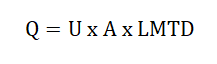 where Q = overall heat transfer rate
U = Overall heat transfer coefficient
A= Overall heat transfer surface area
LMTD = Logarithmic Mean Temperature Difference
Overall Heat Transfer Coefficient Equation
The overall coefficient is the reciprocal of the overall resistance to heat transfer, which is the sum of several individual resistances. The following equation can give the overall heat transfer coefficient in case of heat exchange across the heat exchanger tube.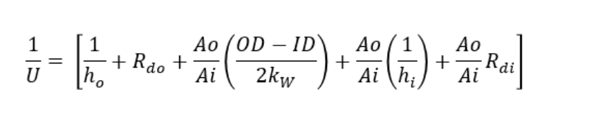 These individual coefficients will depend on various factors such as type the of the heat transfer process, properties of the fluids, flow rates of fluids, flow arrangements, etc.
Check the sample problem to calculate overall heat transfer coefficient.
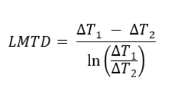
Logarithmic Mean Temperature Difference Calculation
Log mean temperature difference can be calculated by,
 Where,
ΔT1 → the temperature difference between hot and cold fluids at one end of the heat exchanger
ΔT2 → the temperature difference between hot and cold fluids at the other end of the heat exchanger.
Check the sample problem to calculate log mean temperature difference.
To calculate LMTD and correction factor quickly, use this calculator.
In addition, the process of selecting the heat exchanger is also determined by the thermal design calculation which can be done using the design software. It will give the overall heat transfer coefficient, the log mean temperature difference and the pressure drop across the heat exchanger.
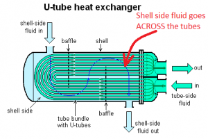
These are the basic equations used in the design of heat exchangers. Apart from this, there are other design equations. To check details of design equations for shell and tube heat exchanger, click here.
Design Procedure
The design of a heat exchanger starts with defining the process parameters such as operating temperature and pressure, total heat transfer rate required, maximum allowable pressure drop on the hot side as well as the cold side, inlet/outlet temperature of hot and cold fluid.
The Design of a heat exchanger is necessarily a trial-and-error procedure. Steps for designing a heat exchanger are discussed below.
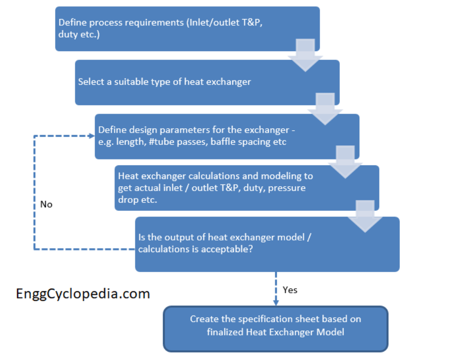
- Initially, we have to define the heat transfer rate, fluid flow rates and inlet-outlet temperature of hot and cold fluid. Collect the fluid properties which are required such as density, viscosity, and thermal conductivity.
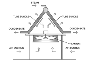
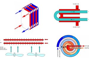
- Then decide the type of heat exchanger to be used based on defined process parameters and the type of fluids being used.
- Select trial value for overall heat transfer coefficient U and based on that calculate Log Mean Temperature Difference and Area required for heat transfer.
- Based on these values calculate the overall heat transfer coefficient. If the calculated value differs notably from the trial value, then use the new value of U for calculating area.
- Calculate the exchanger pressure drop and check whether the value is satisfactory or not. If it is satisfactory proceed to next step of optimizing the design. If the pressure drop is not satisfactory repeat the steps again.
The detailed design procedure of the shell and tube heat exchanger has been discussed in this post.
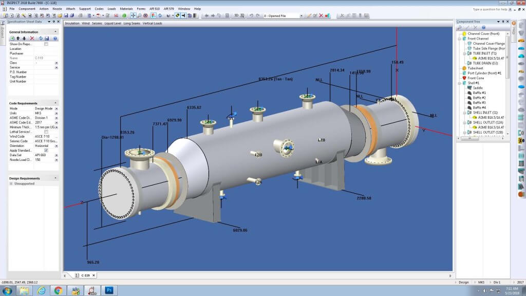
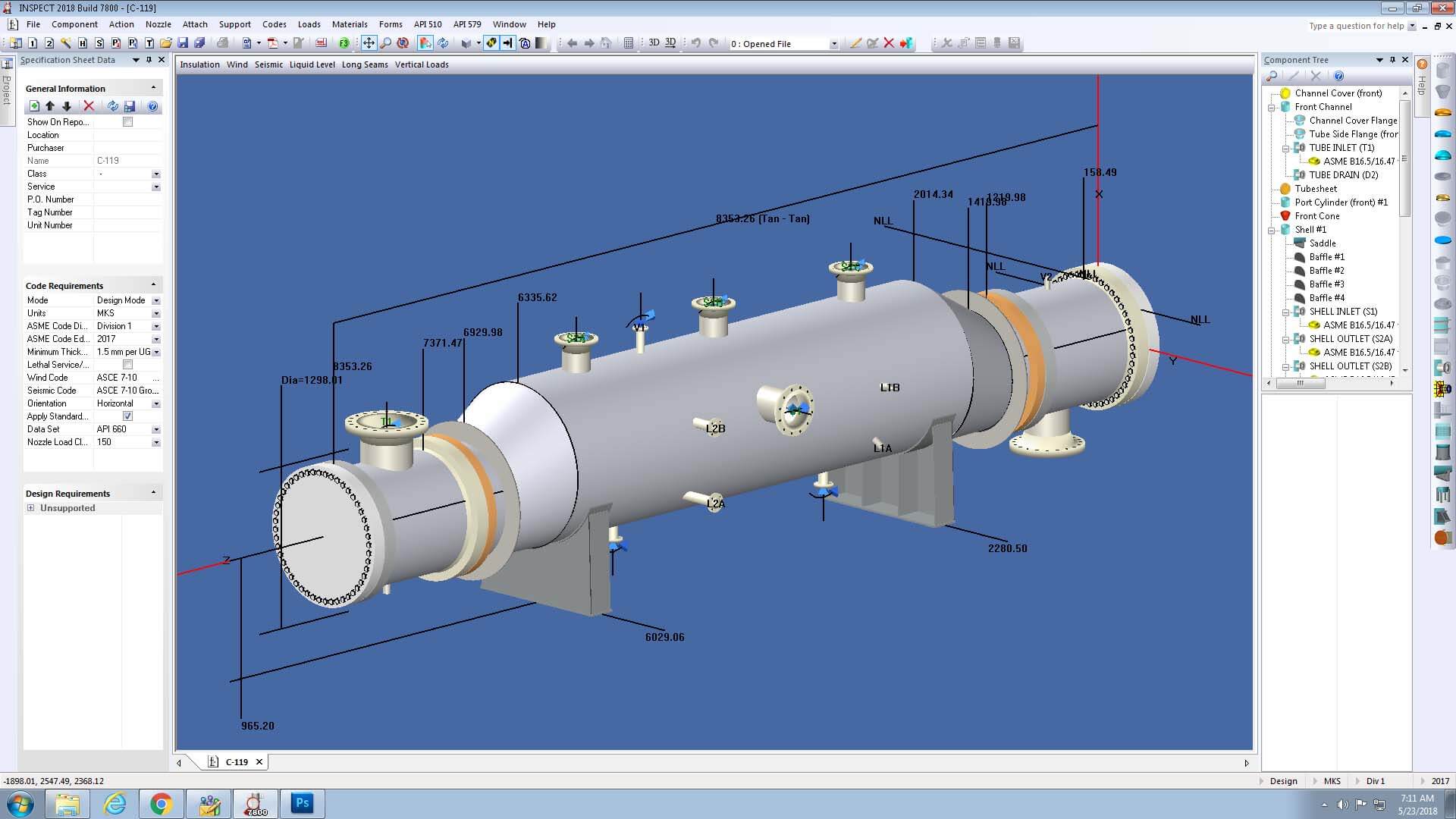
Heat Exchanger Design Software
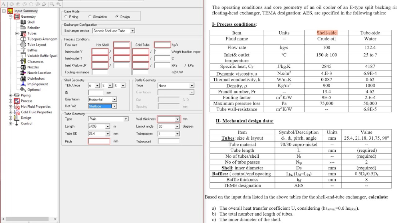
In chemical process industry process engineers use simulation software for designing heat exchanger and to perform complex design calculations. There are many software packages available to design the heat exchanger with each having its unique features and capabilities. In this post we will study few of them.
- Aspen HYSYS: Ansys HYSYS is a very powerful tool for designing heat exchangers as it has ability to perform comprehensive thermal design and rating calculations. It can be used to evaluate heat exchanger performance under various operating conditions, and help to identify the most cost-effective and energy-efficient design options. This can help to reduce the design time and costs, and increase the efficiency of the heat exchanger network. Aspen HYSYS can also simulate heat exchanger network performance in real-time, which can help to optimize the design and identify areas for improvement.
 HTRI: HTRI's Xchanger suite module has capability to design various types of heat exchangers such as shell & tube, plate and frame, air-cooled, Plate fin. This module is used for dynamic simulation of heat exchangers, which allows users to model and simulate heat exchangers under different operating conditions. HTRI uses a mathematical models to simulate heat transfer process and provides accurate performance of heat exchangers. Apart from that HTRI also includes advanced features such as 3D modeling, dynamic simulation as well as optimization tools.
- COMPRESS by Codeware: COMPRESS by Codeware is mainly a software for mechanical design of heat exchanger. And it can be used along with HTRI's Xchanger suite. This is pressure vessel and heat exchanger design software. It has ability to perform calculations according to the most common international codes and standards, such as ASME, API, TEMA for safe operations under any condition.
These are just a few examples, there are many other software packages available, each with its unique features and capabilities. It is best to research and compare different options to find the software that best suits process requirements. Check the detail discussion on the software used for the design of heat exchanger.