It is important to understand the control valves' P&ID arrangement because it helps to identify the valve components. It also helps to integrate the valve with other system components and to troubleshoot potential problems.
Control valves play a crucial role in regulating the flow of fluids or gases in a process system. A valve is a mechanical device that is used to control the flow of fluid in a piping system.
Table of content:
Control Valves – Typical P&ID arrangement
Guidelines to prepare P&ID for the control valve system
Control Valves – Typical P&ID arrangement
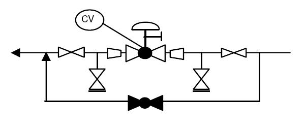
The sample drawing presented here represents a typical arrangement generally used to represent control valves on P&ID.
Guidelines to prepare P&ID for the control valve system
Selection of control valve and actuator symbol
The control valve symbol should be included in the P&ID to represent the valve itself. The actuator symbol should be included in the P&ID to represent the mechanism that operates the valve. Both the control valve and actuator symbols may vary depending on the type of control valve and actuator used.
Depending on the project legend sheets, control valves may be represented by globe or gate valves. Here a globe valve symbol is used. First of all, a proper valve symbol should be selected to represent the control valve as per the project standards.
Reducer / Expander
Generally, the control valve size is smaller than the corresponding line size. This change in diameter should be clearly indicated in the P&ID with the reducer and expander.
Incorporating reducers and expanders in a P&ID arrangement of a control valve can help ensure that the control valve is properly sized and can handle the required flow rates in the process system.
Block valve
In a P&ID arrangement of a control valve, block valves may be included to isolate the control valve for maintenance or repair. Block valves should be provided upstream and downstream of the control valves in case of shutdown and maintenance.
Drain valve
Drain valves are included to remove any accumulated fluids or gases in the system or the control valve. A drain valve is normally provided between the control valve and the upstream block valve. If the control valve is of 'Fail Open' type, this drain valve is sufficient to drain the piping segment. If the control valve is of 'Fail Close' or 'Fail in Position' type, then an additional drain valve is required between the control valve and downstream block valve as shown in the sample drawing.
Bypass
A bypass is a component that can be used in a process system to divert flow around a control valve. Normally, either a bypass or a handwheel is provided for control valves which are under continuous service. If two or more control valves are installed in parallel, a bypass or handwheel is not required.
The choice between providing either a bypass or a handwheel for the control valve is made based on the size of the control valve.
- For control valves bigger than a certain size, the provision of a handwheel is preferred.
- Provision of the bypass with a block valve is preferred for control valves smaller than a certain size.
- For control valves on certain critical services, a spare control valve may be installed on the bypass of the main control valve. This limiting control valve size between the handwheel and bypass is specific for a project and may vary from one project to another.
If the control valve is equipped with a handwheel, then only the drain between the control valve and the upstream block valve is sufficient for draining by opening the control valve using the handwheel. Normally globe valve is selected as the bypass valve on the control valve as it allows better control with the opening.
Additional details such as failure position, tightness class, rating, etc. are also indicated on the P&ID for control valves, as per the project standards.
All the guidelines given here are very general and may be modified as per specific requirements of any particular project.
