Compressors are mechanical devices that increase the pressure of a gas by reducing its volume. They are commonly used in various industries, including HVAC, refrigeration, manufacturing, and power generation, to compress gases such as air, natural gas, and refrigerants. Compressors come in various types, and it's crucial to understand their different features and applications to choose the right compressor for a particular task.
Table of content
1. Types of Compressors
2. Rotodynamic Compressors
2.1. Centrifugal Compressors
2.2. Axial Flow Compressor
3. Positive Displacement Compressors
3.1. Rotary Compressors
3.2. Reciprocating Compressors
Types of Compressors
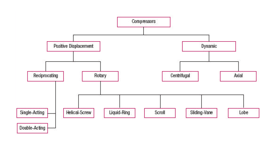
Different types of compressors are classified into two basic categories: Rotodynamic compressors and Positive Displacement compressors. These two broad classes can be further split as:
Rotodynamic compressors
1. Centrifugal compressors
2. Axial flow compressors
Positive Displacement compressors
1. Rotary compressors
2. Reciprocating compressors
Check this compressor classification chart for more understanding.
Rotodynamic compressors
These compressors have rotating equipment parts imparting momentum to the gas particles which is later converted to pressure. For the rotodynamic type of compressors the flow is continuous. These compressors are often smaller in size and produce much less vibration than the positive displacement compressors.
Centrifugal compressors
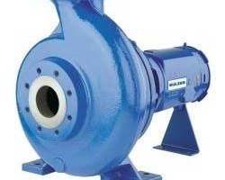
These compressors operate with the same principle as that of the centrifugal pumps. The gases come on from an axial direction to the rotating compressor impeller, which then imparts a radial velocity to the gas particles. These particles then hit the diffuser where the velocity is converted to pressure head. The impellers usually operate with high rotational velocities, typically in the range of 9000-15000 RPM for compressors used in chemical industry. The compressors can have either a single casing with multiple stages or multiple casings with intercoolers between them to reduce the power required to drive the compressors. The compressors are typically driven by gas / steam turbines or electric motors.
The stable operating region for a centrifugal compressor occurs between the ‘surge point’ and the ‘choke point’. Surge point corresponds to minimum flow of stable operation. Surge point is characterized by the reversal of main flow in the compressor, excessive vibration and sound coming from the compressor. Choke point of a compressor at a given operating speed occurs at the maximum flow limit.
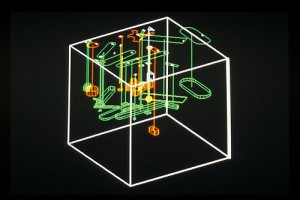
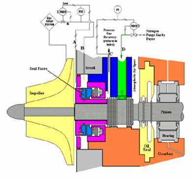
The given figure gives an idea of the structure of a centrifugal compressor. Check this post for detailed study of centrifugal compressors.
Axial Flow compressors
These compressors are primarily used for applications involving large gas flowrates and relatively low outlet pressures, as compared to centrifugal compressors. Axial flow compressors are usually more efficient than centrifugal compressors.
An axial flow compressor consists of a large number of blades attached to a rotating blade with stationary adjustable blades fixed to the compressor casing. This arrangement of blades creates multiple stages resulting in high efficiency and pressure ratio per casing. The operation of an axial flow compressor is governed by the rotational speed of the blades.
The stable operating range for an axial flow compressor is however narrow, compared to the centrifugal compressors. Typical revolution speeds for axial compressors are in the range 1000-3000 RPM.
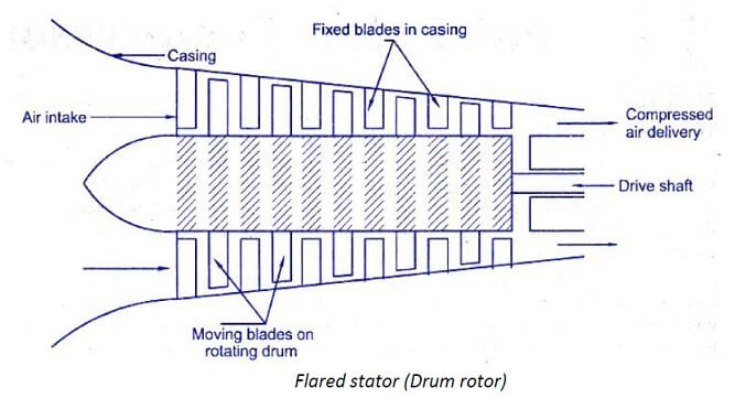
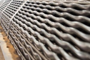
The given figure gives an idea of the structure of a axial compressor. This post contains an overview of axial compressors including their working, advantages, disadvantages, as well as their various applications.
Positive displacement compressors
Positive displacement compressors are mechanical devices used to increase the pressure of a gas by reducing its volume. The major advantage of positive displacement compressors is that they deliver a constant flow of gas at a high pressure.
Positive displacement compressors operate with fixed volumetric gas flows but they can achieve a range of differential pressures. They can be further classified between ‘rotary compressors’ and ‘reciprocating compressors’.
Check this post to study working principle of positive displacement compressors along with its types, advantages and disadvantages.
Positive displacement compressors are available in two main types: reciprocating compressors and rotary compressors.
Rotary compressors
There are many variants of rotary type compressors depending on the details of the mechanism employed. But all of them have two things in common – fixed volumetric flow and one or more rotating shafts. Following schematics are very explanatory of the various mechanisms of rotary type positive displacement compressors.
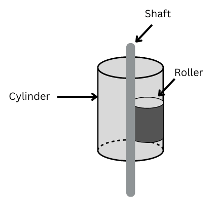
Learn more about rotary compressors and check details of different types of it including liquid ring, scroll, helical screw, sliding vane and lobe in the given post.
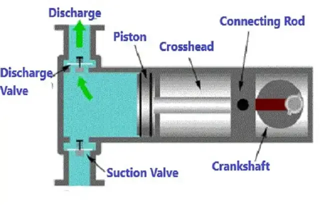
Reciprocating compressors
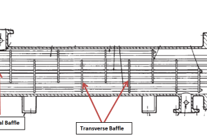
Reciprocating type of compressors is typically used for applications involving low gas flows and high discharge pressures. These compressors can give develop compression ratios as high as 10 per stage depending on the allowable discharge gas temperature. Following pictorial is very explanatory of the mechanism of a reciprocating type compressor.
The figure shows Double acting two-stage reciprocating compressor. Check this post for more detailed illustration of reciprocating compressors.