In this article, we will take a deep look at the shell & tube heat exchanger pressure drop, why it is important, how to calculate it and what factors affect the pressure drop.
Table of Content:
Shell and tube sides of the exchanger
Pressure drop on shell side
Tube side pressure drop
Shell & tube heat exchanger pressure drop calculation
Factors affecting heat exchanger pressure drop
Shell and tube sides of the exchanger
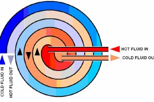
Shell and tube heat exchangers are very popular and widely used in the process industry, thanks to their versatility. They consist of metal tubes passing through another metal enclosure, which is referred to as the 'shell'.
So in shell and tube exchanger, we have two compartments shell side and tube side for housing either one of the hot or cold fluids on either sides of the exchanger. The fluid allocation on either sides is decided based a few factors such as corrosive or fouling nature of a fluid.
Pressure drop on shell side
It is very common to use baffles in the shell side of shell and tube exchanger. They cause the shell side fluid to go across the tubes. This causes 'cross flow' conditions and promotes the overall heat transfer.
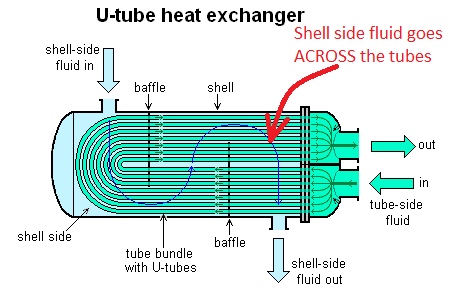
But at the same time, the shell side fluid has to overcome the additional obstacles in the form of the tube bundle. This causes turbulence and excess pressure loss on the shell side of the exchanger.
Some times the turbulence is preferred. For example, it is common to place a more viscous fluid on the shell side. The resulting turbulence helps in an improved heat transfer coefficient on the side of the viscous fluid.
Tube side pressure drop
In contrast to the shell side, flow on the tube side is much better streamlined, hence resulting in minimal pressure drop.
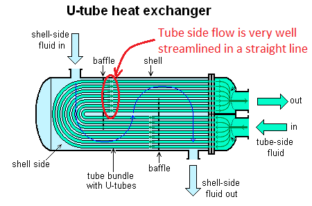
The overall tubeside flow gets divided into a number of smaller tubes. Hence the pressure drop on tube side can be further managed by changing the tube size or increase / decrease the number of tubes. Due to the lower pressure drop on tube side, it is preferable for a service where we have a small allowable pressure drop across the exchanger.
Shell & tube heat exchanger pressure drop calculations
Problem Statement: Calculate the tube side & shell side pressure drop for the following heat exchanger specification,
Process fluid = water
Inlet pressure = 4 barg
Inlet temperature = 500C
Outlet temperature = 300C
Tubeside flowrate = 50000 kg/hr
Number of tubes = 25
Tube ID (internal diameter) = 1 inch
Tube length = 3.5 m
Shell diameter =22 inches
Number of baffles = 32
Baffle spacing = 6 inches (reference - guide to optimize baffle spacing)
Pitch = 1.25 inches, triangular pitch
Shellside roughness = 0.06 mm
Tube side pressure drop calculation
Calculation of tube side pressure drop for a heat exchanger is quite straightforward. Since the pressure drop in individual tubes is very easy to calculate using established practices for calculation of pressure drop across tubes and pipes. Total flow on the tubeside can first be divided by number of tubes and pressure drop across a single tube can be calculated using Darcy-Weisbach equation. This corresponds to the tubside pressure drop. Problem solving is performed in following 2 basic steps.
Step 1. First step of problem solving requires determination the important physical properties of given fluid (water) at given temperature and pressure conditions. Since, water density will be lowest at inlet temperature (500C), which corresponds to highest volumetric flow. Hence for conservative pressure drop estimate, physical properties of water are calculated at the inlet conditions. Using EnggCyclopedia's Liquid Density Calculator,
water density at 500C = 988.0 kg/m3 Using EnggCyclopedia's Liquid Viscosity Calculator,
water viscosity at 500C =0.53 cP
Step 2. Total volumetric flow = 50000 kg/hr ÷ 988.0 kg/m3 = 50.61 m3/hr Volumetric flow in each 1" tube = 50.61 ÷ 25 = 2.02 m3/hr Pressure loss per unit length of the tube is then calculated using EnggCyclopedia's pressure drop calculators for pipes and tubes. This calculator is based on Darcy-Weisbach equation.
Pressure loss across a single tube (ΔP/L) = 6.17 bar/km

Tube length (L) = 3.5 m
Tubeside pressure drop (ΔP) = 6.17 × 3.5 / 1000 = 0.0216 bar
Alternative Solution
Another alternative is to directly use EnggCyclopedia's Heat Exchanger Tube side Pressure Drop Calculator. All the inputs given in the sample problem statements are given to the calculator and pressure drop across the tubeside is calculated as output. This calculator uses the same basic steps discussed above and hence the answer also matches with the figure above (0.0216 bar) . The following image is a snapshot of this direct calculation of tubeside pressure drop.

Shell side pressure drop calculation
Calculation of shell side pressure loss is not as straightforward as the tubeside pressure drop calculation. Presence of baffles in the shell poses a challenge in calculation of the pressure drop on shell side. The shell side has to be approximated as a series of tube banks connected by window zones, for estimating the exchanger shellside pressure drop. Exchanger pressure drop has to be a summation of pressure drop estimated for crossflow across the tube banks and pressure drop estimated for window zones. These pressure drop estimation values have to be corrected by accounting for leakage through baffles and bypassing of tube bundles.
The sample problem presented here using a simplistic approximation which holds quite accurate for large tube bundles. Problem solving is performed in following 4 basic steps.
Step 1. First step of problem solving requires determination the important physical properties of given fluid (water) at given temperature and pressure conditions. Since, water density will be lowest at inlet temperature (500C), which corresponds to highest volumetric flow. Hence for conservative pressure drop estimate, physical properties of water are calculated at the inlet conditions. Using EnggCyclopedia's Liquid Density Calculator,
water density at 500C = 988.0 kg/m3 Using EnggCyclopedia's Liquid Viscosity Calculator,
water viscosity at 500C =0.53 cP
Step 2. Next the effective area for the crossflow across tubes between baffles is calculated using following equation,
Effective Area = Ae = Ds × Bs × (P-Dt) ⁄ P
where, Ds = shell diameter
Bs = Baffle spacing
P = pitch (distance between center axes of two adjacent tubes)
Dt = Tube diameter
For our case, Ae = 0.0341 m2
Velocity of the crossflow then becomes,
V = Mass flow/(ρ×Ae×3600)
V = 50000/(988×0.0341×3600) m/s
V = 0.4127 m/s
Step 3. Next, the effective diameter of fluid path is determined using following approximation,
De = 4 × (P2 - (π Dt2/4) ) / π Dt
De = 0.0484 m
And the factor fk is then calculated as a function of Reynold's number,
fk = 1.79×(ρ×V×D/μ)-1.9
fk = 0.2424 3.7×10⁻⁹
Step 4. The shell side pressure drop is finally calculated using the following equation,
ΔP = ( (N+1)×fk×Ds×ρV2 ) / ( 2×De )
where, N = number of baffles
ΔP = 0.0777 bar
Alternative Solution
Another alternative is to directly use EnggCyclopedia’s Heat Exchanger Shell side Pressure Drop Calculator. All the inputs given in the sample problem statements are given to the calculator and pressure drop across the heat exchanger shell side is calculated as output. This calculator uses the same basic steps discussed above and hence the answer also matches with the figure above (0.0778 bar) . The following image is a snapshot of this direct calculation of tubeside pressure drop.

Here are some resources to help you with accurate calculations for pressure drop across a shell and tube exchanger.
Calculators
- This calculator is for shell side pressure drop calculation. You will need to input basic geometrical details of the shell side construction and fluid properties.
- You can use this calculator to determine tubeside pressure drop. The required inputs are - fluid properties, tube size and length.
Note that the linked calculators are for demo. To access the actual working calculators, you will need to create a login on EnggCyclopedia.
Factors affecting heat exchanger pressure drop
The pressure drop across a shell and tube heat exchanger is mainly a function of the heat exchanger structure and shell & tube arrangement.
When you are designing a new shell & tube exchanger, you can use the pressure drop calculations to verify that the selected design satisfies your process requirement of allowable pressure drop across the exchanger. Otherwise you can change the design parameters to lower the pressure drop and try again.
Here are some factors that you can adjust to manage the pressure drop across shell and tube heat exchanger.
- When you want to lower the pressure drop on shell side, try increasing the baffle spacing. But keep an eye on how it changes the overall heat transfer rate. Increasing the baffle spacing will lower the heat transfer rate. Here are some more details about optimizing the baffle spacing.
- If you have a very limited allowable pressure drop for one fluid, think of putting that fluid on the tube side. If the other fluid (on shell side) is not dirty or corrosive, this may work very well.
- If you have excess pressure drop on the tube side, try increasing the tube size of adding more number of tubes.