Shell and tube heat exchangers are very commonly used as preferred heat transfer equipment in the process industry. This type of heat exchangers consists of metal tubes passing through another metal enclosure, which is referred to as the 'shell'. So typically we have a fluid on shell side and anther fluid on the tube side. Heat transfer between the two fluids occurs across the tube walls.
In general, it is quite easy to have different configurations of the shell and tube arrangement to create many more subtypes within this broad category of heat exchangers. This versatility is one of the reasons why shell and tube exchangers are so popular among process design engineers.
Table of content:
- Shell & tube heat exchanger diagram
- Components of shell & tube exchangers
- Shell and Tube heat exchanger types
- Design of shell & tube exchanger
- Typical shell & tube exchanger P&ID diagram
- Typical heat exchanger datasheet
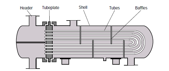
Shell & tube heat exchanger diagram
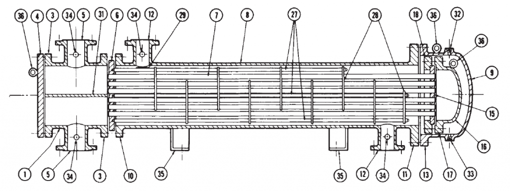
This post contains diagram that shows the structure of a TEMA style shell and tube heat exchanger.
This diagrams illustrates all the important parts in the construction of a shell & tube heat exchanger, as per the TEMA standards. It also gives you the exact correct nomenclature for each of those parts.
Components of shell & tube exchangers
These are some exchanger parts are important for the overall design of the exchanger -
- shell
- shell cover
- tubes
- channel
- channel cover
- tubesheet
- baffles
- nozzles
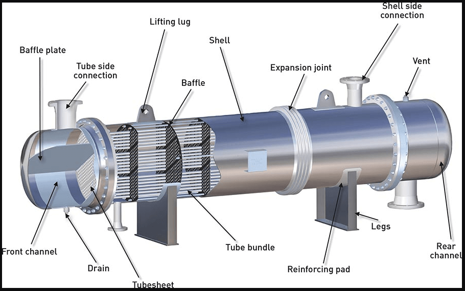
This post illustrates all the important parts in the construction of a shell & tube heat exchanger, as per the TEMA standards. Click button for the detail understanding of all parts.
Shell and Tube heat exchanger types
There are two ways of classifying these exchangers -
A. based on the construction or structure of shell and tube sides
B. based on the service
Structure based classification of shell and tube exchangers
TEMA standards describe these various components in detail. A shell & tube heat exchanger (STHE) is divided into three parts:
- The front end
- Shell
- Rear end
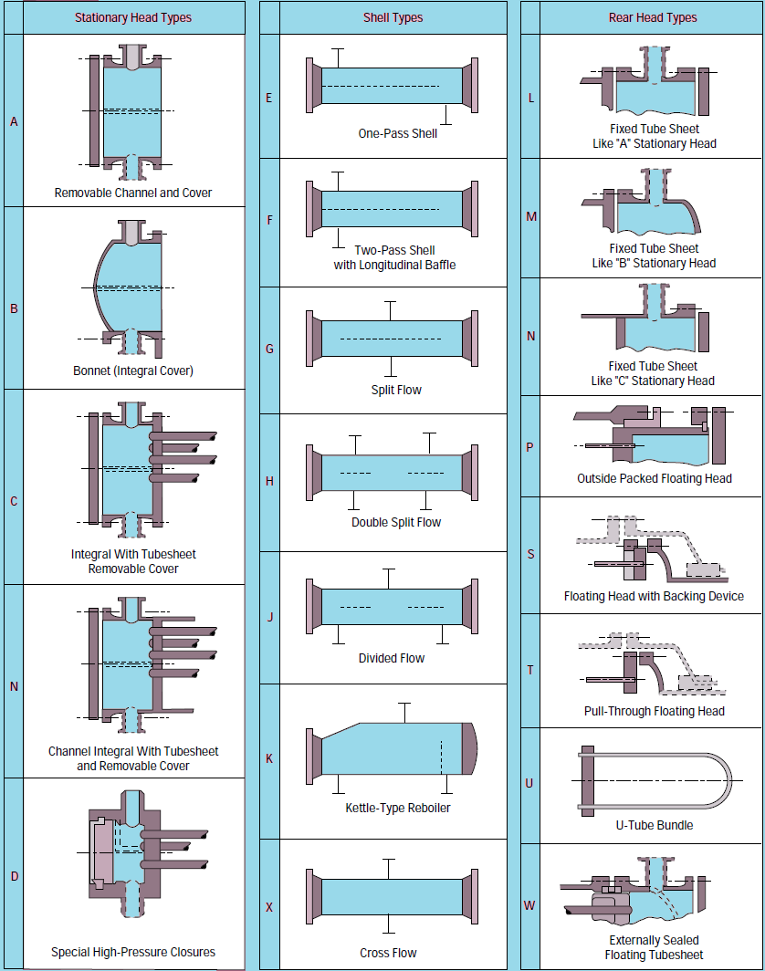
Following table from the TEMA standards explains the different possible configurations for each of the 3 broad parts.
Other smaller parts are listed in this detailed diagram of a shell & tube heat exchanger, along with their correct nomenclature as per the TEMA standards.
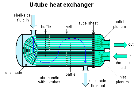
Many different exchanger configurations can be easily created by different combinations of front end, shell and rear end. Moreover depending on how tube bundle is fixed to the front end or rear end cover, we have 3 broad types of shell & tube heat exchanger construction.
- Fixed tubesheet exchangers
- U tube exchanger
- Floating head exchangers
Exchanger types based on the service
Process fluid which is to be either heated up or cooled down in the exchanger, is commonly referred to as the 'service'. The service may be single phase (either gas or liquid) or two-phase (mixture of gas and liquid).
On the other hand one of the fluids (shell or tube side) can be a non process fluid, which is only used for heating or cooling the process fluid. Such stream is known as a 'utility'. Utility can also be either single phase or two phase.
We may have two fluids in the shell and tube exchanger on both - shell side and tube side. That leads to multiple combination of services -
- single-phase (both shellside and tubeside)
- condensing (one side condensing and the other single-phase)
- vaporizing (one side vaporizing and the other side single-phase)
- condensing/vaporizing (one side condensing and the other side vaporizing)
Based on such combinations, we can have following types of exchangers -
- Heat exchanger: fluids on both sides are single phase process fluids
- Cooler: one stream is process fluid the other is a colder utility such as air or cooling water
- Heater: one stream a process fluid and the other a hot utility, such as steam or hot oil
- Condenser: on one side we have two phase flow of with gas at its dew point. This gas is condensed using a cold utility on the other side such air or cold water.
- Chiller: one stream a process fluid being condensed at sub-atmospheric temperatures and the other a boiling refrigerant or process stream.
- Reboiler: one stream a bottoms stream from a distillation column and the other a hot utility (steam or hot oil) or a process stream.
Selecting a heat exchanger type
The structure of a shell and tube exchanger is decided based on a number of factors like -
- the nature of process fluids on both sides
- flow rates on both sides
- expected nature of operations and maintenance
- temperature difference on both sides and the required heat transfer area
This post illustrates all the important types of shell & tube heat exchanger, as per the TEMA standards. Click button for the detail understanding of all types.
Design of shell & tube exchangers
Design of shell and tube exchangers is commonly governed by the standards created by TEMA (Tubular Exchangers Manufacturers Association).
Shell & tube exchanger calculations
Thermal design of the heat exchanger is done to determine the overall heat transfer area required and then to decide the size of the exchanger in terms of shell ID, number tubes and their configuration etc.
The heat transfer across a heat exchanger is governed by the following equation -
Q = U × Aoverall × LMTD ....... Equation (i)
Here,
Q is the overall heat transfer rate across a given heat exchanger (in Watts)
U is the overall heat transfer coefficient for that exchanger
Aoverall is the overall effective heat transfer area between the hot and cold sides of the exchanger
LMTD is the logarithmic mean of temperature difference
Most commonly, heat exchanger design software is used to simulate the performance of a shell & tube exchanger design and then to rate it. But some times, you may prefer to (or have to) do the design calculations manually.
Heat transfer coefficients
You must be careful to distinguish between the local heat transfer coefficients on shell or tube side AND the overall heat transfer coefficient.
Local heat transfer coefficients are valid only locally and they change along the path of the exchanger. Whereas overall heat transfer coefficient is defined for the whole exchanger, it is independent of the fluid path in the exchanger.
Local coefficients must be multiplied with local temperature difference to get the local heat transfer.
Overall heat transfer coefficient is multiplied by LMTD to give you the overall heat transfer rate.
Logarithmic Mean Temperature Difference
Logarithmic Mean Temperature Difference (LMTD) is an indicator of the average temperature difference between the hot and cold fluids in a heat exchanger.
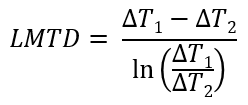
This equation for LMTD is widely used by process design engineers to get the average temperature difference for heat exchanger sizing calculations. But sometimes this LMTD equation can also fail. That happens when the temperature difference is constant throughout the length of the heat exchanger. You must be careful in such cases to directly use that constant temperature difference value, instead of getting trapped in the formula that is prone to fail.
Here is a list of all important equations that govern the design of a shell and tube heat exchanger.
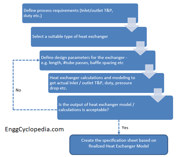
Shell & tube exchanger design procedure
Thermal design for a shell & tube exchanger is done by the process design engineers, using a process simulation software like HYSYS. Following the process design, mechanical design engineers can refer to applicable design standards to finalize the structural details of the heat exchanger.
Design guidelines and tips for shell & tube exchanger
- The shell side baffles are used to promote crossflow and enhance the heat transfer between the two fluids. The spacing between shell side baffles has an important impact on the degree of heat transfer. You can use these guidelines to select the optimal shell side baffle spacing. It is generally recommended to consider baffle spacing between 0.3 to 0.6 times of shell ID, as per the TEMA standards.
- Follow the design guidelines for the fluid allocation in a shell & tube heat exchanger, i.e. to decide which fluid should go to the shell side and which to the tube side.
This article is a high-level tutorial on shell & tube heat exchanger design procedure. The article contains a study on finalizing the process parameters and preparing the process specification sheet for the new exchanger.
Typical shell & tube exchanger P&ID diagram
Finally, only designing and installing a heat exchanger is not enough, process engineer must also carefully design the piping and instrumentation around a shell & tube heat exchanger.
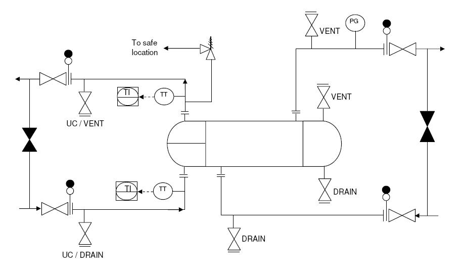
Here is a typical piping and instrumentation diagram (P&ID) for a heat exchangers. It will give you useful pointers for designing a heat exchanger system and also for the process control, safety devices, piping and instrumentation around that heat exchanger.
And when you are actually creating a heat exchanger P&ID, you will find these typical heat exchanger P&ID symbols quite handy.
Typical heat exchanger datasheet
Along with the P&ID Another important document for the design of heat exchanger system is - the datasheet. The preliminary datasheet prepared by the process design engineer is normally called the 'process datasheet'. Then the equipment design engineer ads more details of the structure of the exchanger to create the 'mechanical datasheet' or equipment datasheet.
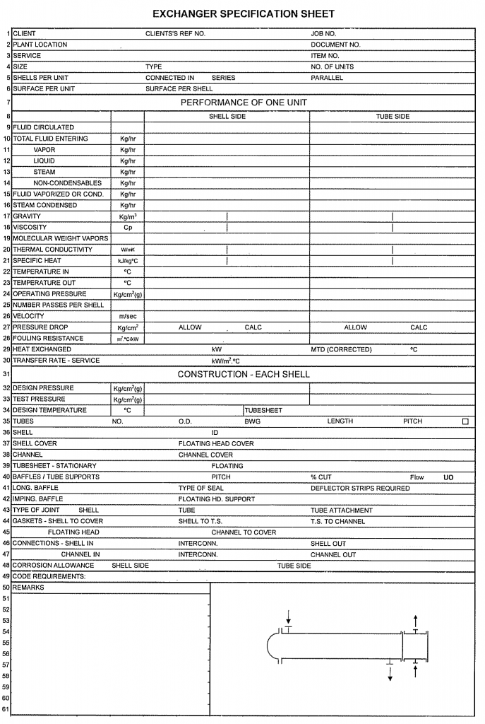
Here is a typical datasheet for a shell & tube heat exchanger. You can use this template to create a new datasheet for your project or simply to understand the different parameters that are important to the design of a shell and tube exchanger.