This article is a high level tutorial on shell & tube heat exchanger design procedure. We will mainly look at finalizing the process parameters of a new shell & tube exchanger and preparing the process specification sheet for the new exchanger.
Shell and tube heat exchangers are the most popular and widely used heat transfer equipment in process industry. This is mainly because of the versatility of shell and tube exchangers, based on different types of shell & tube exchangers that can be easily created by changing the shell and tube arrangement.
Process and mechanical design
The first step in the engineering design of a new heat exchanger is to finalize the process parameters such as -
- Operating temperature and pressure
- Design temperature and pressure
- Heat duty, which is the total required heat transfer rate
- Inlet / Outlet temperature for hot fluid
- Inlet / Outlet temperature for cold fluid
- Maximum allowable pressure drop on hot side
- Maximum allowable pressure drop on cold side
- Type of heat exchanger to be used
- Shellside / tubeside fluid selection (i.e. whether hot / cold fluids should go to shell side or tube side)
Based on this information, mechanical engineers then prepare a mechanical datasheet that can be used by the heat exchanger manufacturer for final fabrication. The mechanical datasheet is based on the guidelines provided by TEMA standards which are developed by Tubular Exchanger Manufacturer's Association (TEMA).
Iterative heat exchanger process design procedure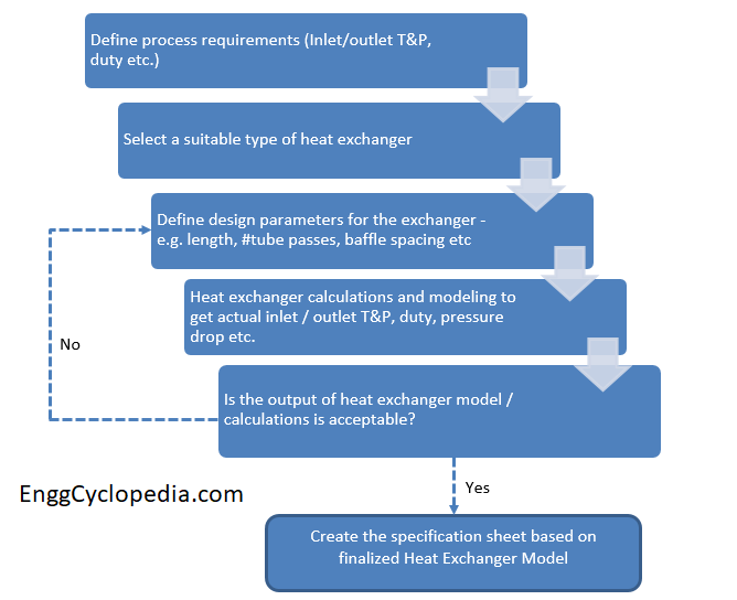
Process design of a shell and tube heat exchanger is an open ended problem. There are more parameters (or variables) than there are constraints. Hence it is possible for us to fix some of those parameters to get a cost effective and efficient heat exchanger design.
But which parameters to fix and to what values?
That is why process design for a heat exchanger is often done in an iterative manner and the optimal design is found by trying out different heat exchanger design parameters.
With that in mind, let's go through the steps involved in shell & tube heat exchanger design procedure.
Steps for heat exchanger design procedure
1. Define the essential process requirements
First and foremost, we must clearly define the primary objectives for the new heat exchanger equipment.
There are certain process parameters which must be fixed. For example, process fluid flow rate, inlet / outlet temperature, operating and design pressure values, maximum allowable pressure drop etc. These parameters are fixed inputs to our heat exchanger design calculations and they are also the constraints.
2. Select suitable type of heat exchanger
Based on the nature of the process fluid (service), operating temperature and pressure, allowable pressure drop across the exchanger, available utility, flow rate etc, you need to select the most suitable type of heat exchanger.
When you have selected a shell and tube heat exchanger, you also need to decide which fluid should go to the shell side and which one to the tube side. This is also decided based on the given process conditions and the nature of two hot and cold fluids.
At this stage, it is also recommended to pay due attention to what utilities can be used and the corresponding approach temperature value. Any required changes with respect to utility or heat exchanger type, should be made at this stage.
3. Fix some of the design parameters to create a heat exchanger model
As the heat exchanger design is going to be an iterative process, we need a starting point. We need to fix some of the design parameters like, no. of tube passes, length of the heat exchanger, shell ID, baffle spacing etc. to some tentative values.
This is a starting point for out iterative model and these values will change as we examine the design against our process requirements. But it is important to select (guess) the initial parameters as close as possible to the final design. That way, we will need the minimum number of iterations to get to the final design.
You can also use these resources for manually doing the heat exchanger calculations, before going to a modeling software.
4. Rating of the heat exchanger design
Next, create a model using a heat exchanger simulation software. Use this model to check that all our process requirements from step1 are met. For example, check the outlet temperature of process fluid and pressure drop values on shell and tube sides. Are they within the constraints set by our process requirements?
If not, then check which process requirements are not met. Accordingly change the heat exchanger design parameters and go back to step3.
With the new design parameters, re-adjust your heat exchanger model and repeat the simulation calculations. Then you can again check the rating. This process will repeat till you find a heat exchanger model that can satisfy all your process requirements.
5. Create specification sheet with finalized heat exchanger design
When the heat exchanger rating does satisfy your process requirements, you can capture all the details in a process datasheet. Send this data sheet to the mechanical equipment design engineer, so he can prepare the heat exchanger specification sheet as per TEMA standards.
Shell & tube heat exchanger fluid allocation
As discussed in the first point for designing a new shell and tube heat exchanger, you will need to decide where the hot / cold fluid streams must be places. Which should go through shellside and which will go through the tubes. This decision is commonly referred to as fluid allocation for the shell & tube heat exchanger.
There are three important aspects that need to be considered when designing a new exchanger -
- Achieving the required heat transfer while maintaining the equipment cost below a certain limit
- Ensuring that the new heat exchanger is easy to maintain
- Making sure that pressure drop values for the fluids on shell and tube sides, don't result in excess pumping costs
Preferred fluids on the tube side
Considering the important features of the tube bundle in an exchanger, following fluid services are better suited for the tube side.
- Fouling or corrosive fluid service is kept on the tube side, since mechanical cleaning of the inner tube surface is easier.
- It is cheaper to replace corroded tubes, than the shell cover. Hence corrosive service must be kept on the tubeside.
- High pressure fluid is also kept on the tubeside, since tubes with higher pressure rating are cheaper than the shell with high pressure rating material.
- Toxic services are kept on the tubeside to increase their containment.
- Fluids where you have a low allowable pressure drop are also kept on the tubeside.
- Cooling water is generally kept on the tubeside, because it tends to corrode carbon steel and form scale.
Preferred stream on the shell side
Following fluid services are better kept on the shell side, considering charecteristics of shell.
- When more viscous fluid is kept on the shell side, the increased turbulence will result in increased heat transfer coefficient and improved overall heat transfer.
- Fluid with higher flow rate is generally preferred to be kept on the shell side.
- Service where a large temperature change is desired is also kept on the shell side, where temperature change can be achiever by increasing the length of the exchanger.
Piping and instrumentation around the heat exchanger
Apart from the designing the heat exchanger equipment itself, you would also need to design the piping and instrumentation around the heat exchanger for appropriate maintenance, safety and process control measures.
A process engineer creates a P&ID diagram to guide the piping and instrumentation engineers with their final design of surrounding piping and instrumentation. Here are detailed guidelines for creating a P&ID diagram for heat exchanger.
References and resources
- This shell & tube heat exchanger diagram gives a detailed list of all its parts with exact nomenclature as per TEMA standards.
- A list of all the important equations for shell & tube heat exchanger design.