In this article, we will take a detailed look at the equations required for shell and tube heat exchanger sizing calculations and design.
Shell and tube heat exchangers are widely used and very popular in the process industry, due to their versatility. Different types of shell and tube exchangers can be easily configured by changing the shell and tube arrangement.
INDEX
- Shell & tube heat exchanger design procedure
- Heat exchanger equations
- Calculations for shell & tube exchanger design
- Software for heat exchanger sizing calculations
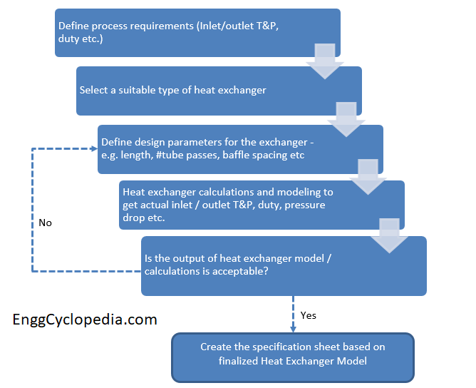
Shell & tube heat exchanger design procedure
Shell and tube heat exchanger design is an iterative process, which goes through the following steps.
- Define process requirements for the new exchanger
- Select a suitable type of shell and tube exchanger
- Define design parameters such as - number of tube passes, tube size, shell ID etc.
- Heat exchanger calculations and modeling to get the output - outlet hot/cold fluid temperature, heat transfer rate, pressure drop on shell/tube sides etc.
- Check of the output is in accordance with the process requirements
- If the output is as per process requirements and cost is within budget then finalize the process design and prepare a heat exchanger specification sheet
- If the design does not match with either the process requirement or if it is over budget then go back to step 3, change the design parameters and repeat this process again.
There are a few equations that are very important for the calculations that we need to perform during heat exchanger design process.
Shell and tube heat exchanger equations
Here is a list of all the important shell and tube heat exchanger equations.
Overall heat transfer equation
Overall heat transfer in any exchanger is governed by the following equation -
Equation-1
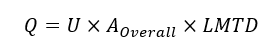
where, Q = overall heat transfer rate
U = Overall heat transfer coefficient
AOverall = Overall heat transfer surface ares
LMTD = Logarithmic Mean Temperature Difference
LMTD equation
The logarithmic mean temperature difference is an average quantification of the temperature difference between the shell and tube sides. It is calculated with the following equation.
Equation-2
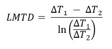
Where,
ΔT1 → the temperature difference between hot and cold fluids at one end of the heat exchanger
ΔT2 → the temperature difference between hot and cold fluids at the other end of the heat exchanger.
LMTD with the Correction factor
However the LMTD is valid only for heat exchanger with one shell pass and one tube pass. For multiple number of shell and tube passes the flow pattern in a heat exchanger is neither purely co-current nor purely counter-current. Hence to account for geometric irregularity, Logarithmic Mean Temperature Difference (LMTD) has to be multiplied by a Mean Temperature Difference (MTD) correction factor (FT) to obtain the Corrected Mean Temperature Difference (Corrected MTD).
Equation-3
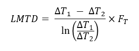
This correction factor calculator will help you to quickly calculate the LMTD correction factor for a shell and tube exchanger with multiple shell or tube side passes.
To check detailed calculation of LMTD, click here.
Number of tubes based on the heat transfer area required
The number of tubes needed in shell & tube exchanger (NT) can be calculated using the following equation, based on overall heat transfer area requirement.
Equation-4
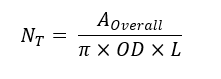
Where, we get the AOverall (overall heat transfer area required) from the heat transfer rate equation (Equation-1).
OD is the outside diameter of selected tube size
L is the total tube length
This equation is quite straight forward based on the geometry of the selected shell and tube heat exchanger.
Tube side fluid velocity
Tube side velocity is important for estimation of Reynolds number on the tubeside and then for getting the heat transfer coefficient for the tube side fluid. We can use the following equation for tube side velocity.
Equation-5
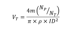
Where, m = mass flow rate on the tube side
NP = Number of tube passes
NT = Number of tubes
ρ = Tube side fluid density
ID = Tube internal diameter
Further, the Reynold's number for the tube side fluid is calculated as,
Equation-6
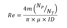
Here, μ is the viscosity for tube side fluid
Overall heat transfer coefficient equation
When we have a handle on the heat transfer area (AOverall) and temperature difference (LMTD), the only remaining unknown in the heat transfer equation (Equation-1) is the overall heat transfer coefficient (U). We can use the following equation to get the overall heat transfer coefficient for a shell & tube exchanger.
Equation-7
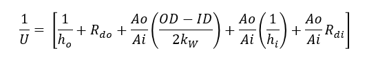
Where, ho = Shell side heat transfer coefficient
hi = Tube side heat transfer coefficient
Rdo = shell side dirt factor
Rdi = tube side dirt factor
OD and ID are respectively the outer and internal diameters for the selected tube size
Ao and Ai are outer and inner surface area values for the tubes
kw is the resistance value for the tube wall
Note, this overall heat transfer coefficient is calculated based on the outer tube surface area (Ao). So it must be multiplied by the Ao value for using in the overall heat transfer equation.
Shell & tube heat exchanger calculations
We already saw that the design of a shell and tube heat exchanger is an iterative process. Often, engineers prefer to use a heat exchanger design software to create a heat exchanger model. You can then use this model to simulate the heat exchanger performance and to verify if it will meet your process requirements.
However, if you decide to manually perform the heat exchanger sizing calculations, you can use this heat exchanger area calculator to be used for reference.
Heat exchanger calculators
Note all of the following calculators are for demo. To access the actual working calculators, you will need to create a login on EnggCyclopedia.
- Here's a shell & tube heat exchanger sizing calculator to help you calculate the required heat transfer area based on inlet/outlet temperature values on shell and tube sides. This calculator is for sizing the tubeside flow based on a fixed shell side flow. Other required inputs are - flow rate, density, viscosity, specific heat values for fluids on shell and tube sides.
- This other heat exchanger are calculator for shell side flow will help you calculate the required surface area as well as the shell side flow, when you have fixed conditions on the tube side. Other required inputs are - flow rate, density, viscosity, specific heat values for fluids on shell and tube sides.
- This quick LMTD calculator helps to quickly get LMTD value for an exchanger.
- Then there is another calculator for LMTD correction factor.
- Apart from these, you will also need to calculate the pressure drop on the shell and tube sides for your process datasheet. This calculator is for shell side pressure drop calculation.
- You can use this calculator to determine tubeside pressure drop.
Apart from these calculators, you can always use a heat exchanger design software to build a model of your heat exchanger design and then to simulate its performance.
Tutorials for shell & tube exchanger calculations
Here are some step by step guided tutorials about how to use those calculators for shell & tube heat exchanger calculations. In these tutorials, we will make use of the shell & tube heat exchanger equations discussed above.
- Calculation of overall heat transfer coefficient
- Calculation of insulation thickness for furnace wall
- LMTD calculation tutorial
Recommended steps
Here are some recommended steps to use the heat exchanger design equations -
- Fix the inlet/outlet temperature values
- Calculate LMTD
- Select a shell and tube heat exchanger (TEMA) tube
- Decide on shell and tube geometry
- Calculate heat transfer area based on selected geometry (AOverall)
- Get the overall heat transfer coefficient (U), using a suitable empirical correlation for given fluid - for example, Sieder-Tate equation
- Calculate the overall heat transfer rate (Q), using Equation-1
- Check of Q matches with the heat lost/gained via temperature change on the hot and cold side. This is the basic energy balance on shell / tube side fluids.
- Check the pressure drop on shell and tube sides. Does is match with the allowable pressure drop as per process requirements?
- If the design is adequate as per process requirements, check the tentative material costs. Are they within budget? During project execution, many engineering and construction teams also use Excel templates for construction project cost control to monitor material costs, labor expenses, budget utilization, and overall project spending throughout the project lifecycle.
- If either of the design or budget checks fail, go back to step 4 and repeat the process till you get a satisfactory shell & tube heat exchanger design.
Tips and pointers for heat exchanger calculations
- The shell side baffles are used to promote crossflow and enhance the heat transfer between the two fluids. The spacing between shell side baffles has an important impact on the degree of heat transfer. You can use these guidelines to select the optimal shell side baffle spacing. It is generally recommended to consider baffle spacing between 0.3 to 0.6 times of shell ID, as per the TEMA standards.
- Heat exchanger approach temperature is an important factor influencing the design of an exchanger. It is advisable to carefully consider the selected utility and corresponding approach temperature, before actually proceeding with the sizing calculations.
Software for heat exchanger sizing calculations
You can use these packaged software tools for heat exchanger sizing calculations, specialized applications such as casting and chemical process simulation. The choice of software will depend on the specific requirements and preferences of engineers and designers in different fields.
- HTRI Xchanger Suite:
- Extensive thermophysical property databases.
- Comprehensive heat exchanger design and analysis tools.
- Detailed rating and simulation capabilities.
- User-friendly interface with drag-and-drop functionality.
- Aspen Exchanger Design and Rating:
- Powerful modeling and simulation capabilities.
- Wide range of heat exchanger types supported.
- Heat exchanger fouling and cleaning analysis.
- Integration with AspenTech's suite of process engineering software.
- Thermal Desktop:
- Advanced thermal analysis and design tools.
- Support for various heat exchanger geometries.
- Integration with CAD software for 3D modeling.
- Heat exchanger optimization and parametric studies.
- ESI ProCAST/QuikCAST:
- Specialized for casting and foundry applications.
- Predictive thermal analysis for heat exchanger molds.
- Solidification and cooling simulation.
- Material property databases for metal alloys.
- COMSOL Multiphysics:
- Multiphysics simulation software for heat exchanger design.
- Flexibility to model complex geometries and heat transfer processes.
- Can be used for various engineering simulations.
- Parametric studies and optimization capabilities.
- Ansys Fluent:
- Computational Fluid Dynamics (CFD) software.
- Detailed analysis of heat exchanger performance.
- Simulates fluid flow, heat transfer, and pressure drop.
- Ideal for advanced heat exchanger design and analysis.
- CHEMCAD:
- Chemical process simulation software with heat exchanger modules.
- Integration with process flowsheet and equipment design.
- Supports a wide range of exchanger types.
- Accurate heat exchanger rating and optimization.