PFD of IGCC Plant
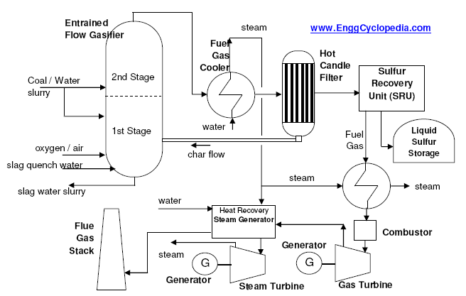
This figure represents a typical a process flow diagram (PFD) of an Internal Gasification Combined Cycle (IGCC) power plant technology featuring an oxygen‐blown, entrained‐flow, refractory lined gasifier with continuous slag removal. Different types of gasifiers can be used in an IGCC plant depending on factors such as fuel type, size of fuel type, ash and moisture content of fuel etc. Apart from different types of gasifiers, different types of gasification processes can be employed in an IGCC plant. These IGCC power plants can be designed to use a range of coal types. Sometimes there might be some limitations of the sulphur content of coal to be used as gasification fuel. The feed can even include the petcoke (petroleum coke) or sometimes biomass.
As shown in the process flow diagram, the coal is first slurried with water and fed to the first stage of the gasifier. Oxygen with a purity of 95% is provided from the Air Separation Unit (ASU) and the coal is partially combusted to maintain a temperature of 1370 °C. Raw fuel gas is produced as the coal chemically reacts with oxygen and steam. The melted ash at the bottom of the vessel is removed while the raw gas is moves to the second gasification stage where this gas reacts with additional coal/water slurry undergoes devolatilization, pyrolysis and partial gasification in order to enhance the raw gas heating value and cool it down as the evaporation of water and endothermic reactions cause the temperature to be reduced. The raw syngas exits the second stage of the gasifier at temperature of 1038 °C and is further cooled in a fire tube boiler, producing high pressure (110 bar) saturated steam. The temperature and pressure values indicated here are for a specific gasifier type and gasification process type and will change according to the process and fuel used.
The gas cleanup system consists of a metallic candle filter system for the removal of fly ash and remaining char particles that are recycled back to the first stage of the gasifier for gasification of residual carbon. In order to achieve the low design values of SO2 emissions, high degree of H2S and COS removal are required in the acid gas removal system (AGR Unit). Implying the necessity to hydrolyse COS. Before the removal of H2S, sour gas is cooled in possibly multiple heat exchangers. The cooled fuel gas is then passed through the conventional H2S removal unit consisting of an absorber column with MDEA solvent. Sulphur is recovered to a purity of 99.99% in a Clausplant. After sulfur recovery the syngas is ready to be combusted for power generation.
For NOx emission control purposes, the syngas is pre‐heated and saturated before it can go to combustor. The combustor can be based on single fuel or dual fuel operation. Dual fuel operation burns syngas and oil, where oil is used during start‐up. Hot gases from the cobustor, enter the gas turbine which is connected to power generator. This is where the actual power generation takes place. The flue gas from the gas turbine is mixed with HP steam generated in fuel gas cooler and these gases are sent to Heat Recovery Steam Generator (HRSG). HRSG uses the residual heat from gases to produce steam which then goes to a steam turbine and generates more power. The Heat Recovery Steam Generator (HRSG) is used to provide maximum super-heating and re-heating temperature. Flue gases from the HRSG are vented through a flue gas stack.
Following table represents composition of syngas produced after gasification in an IGCC power plant.
Table 1: Sample composition of syngas from Entrained Bed IGCC Plant
| Coal | Petroleum Coke | |
| H2 | 34.4 | 33.2 |
| CO | 45.3 | 48.6 |
| N2 | 1.9 | 1.9 |
| Ar | 0.6 | 0.6 |
| CO2 | 15.8 | 15.4 |
| CH4 | 1.9 | 0.5 |
