Heat exchangers are an essential component of many industrial and commercial systems, as they allow for the transfer of heat between two fluids without them coming into direct contact. Properly sizing a heat exchanger is crucial to ensure that it can effectively transfer heat and meet the needs of the system it is being used in. In this post, we'll take a look at details that go into heat exchanger calculations and how to properly size a heat exchanger for your specific system.
Heat Exchanger Design
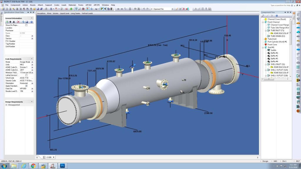
Design of an exchanger involves various types of complex design calculations. Check the post to study the basics of heat exchanger design including theory, equations, design procedure, and design software.
Energy balance calculation
In heat exchanger calculations, energy balance calculation is an important step to determine the heat transfer rate and the thermal performance of the heat exchanger. Energy balance calculation is often done for designing a heat exchanger to determine operating parameters for hot and cold fluids such as - inlet/outlet temperatures and flow rates.
Calculation of heat transfer coefficient
Heat transfer coefficients are a measure of the rate at which heat is transferred between a fluid and a solid surface. The heat transfer coefficients can be determined using a variety of methods, such as using industry-standard values or conducting experiments to measure the coefficient for your specific system.

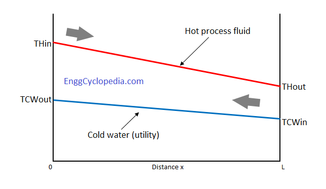
Log mean temperature difference calculation
The Log Mean Temperature Difference (LMTD) is a mathematical formula used in heat exchanger calculations to calculate the temperature difference between the hot and cold fluid streams at different points in the exchanger. As this is an important parameter in the design of a heat exchanger, the process engineer must understand the concept of LMTD very well.
Heat exchanger area
Determining a heat exchanger area is the most important step in the design of a heat exchanger, as it directly impacts the efficiency and performance of the heat transfer process. Heat exchanger area refers to the total surface area available for heat transfer between the hot and cold fluids in a heat exchanger. The heat exchanger area is a measure of the size of the heat exchanger and its capacity for heat transfer. Click on below button to check step by step calculation of the heat exchanger area.
Heat exchanger efficiency
Heat exchanger efficiency is a measure of how effectively a heat exchanger transfers heat from one fluid to another. It is defined as the ratio of the actual heat transferred to the maximum possible heat transfer in an ideal exchanger, under the same conditions. Higher efficiency means that more heat is being transferred, while lower efficiency indicates that less heat is being transferred. Check this post for a thorough study of heat exchanger efficiency.
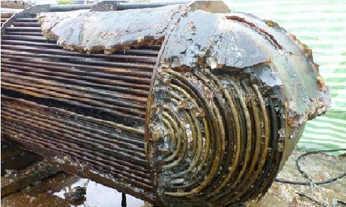
Heat exchanger fouling factor
Fouling is a common problem in different kinds of heat exchangers. Fouling in a heat exchanger refers to the buildup of unwanted materials, such as dust, dirt, oil, salts, or process by-products, on the surface of a heat exchanger.
The heat exchanger fouling factor quantifies the effect of fouling on the reduced heat transfer efficiency. It normally depends on the process fluid or service on any side (shell or tube) of the heat exchanger. As the fouling factors (either on the shell or tube side) increase, the overall heat transfer coefficient will decrease. Check this post to understand the fouling factor thoroughly.
Heat exchanger approach temperature
Approach temperature is the difference between the required outlet temperature of the process fluid and the temperature at which utility is available. Heat exchanger approach temperature indicates the effectiveness of a utility for its intended purpose.
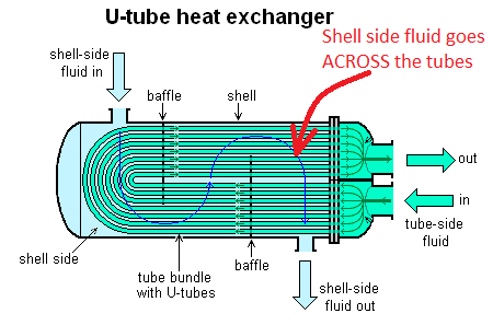
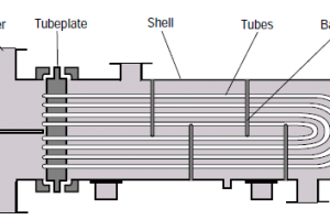
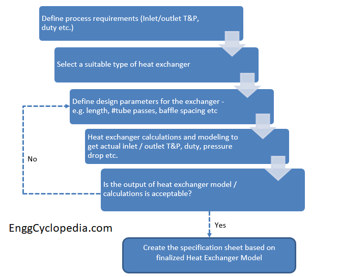
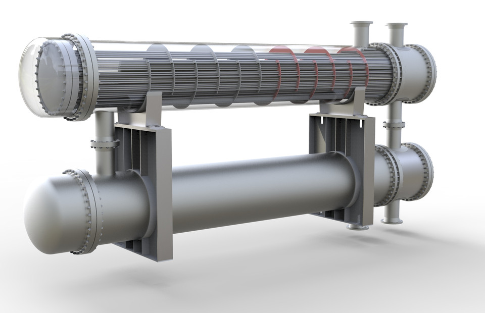
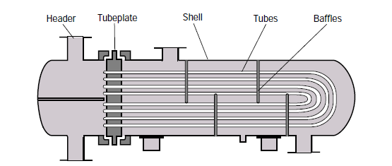
Shell and tube heat exchanger design
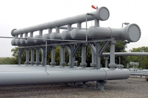
Shell and tube heat exchangers are the most popular and widely used heat transfer equipment in the process industry. This is mainly because of the versatility of shell and tube exchangers. Different types of shell & tube exchangers can be easily created by changing the shell and tube arrangement.
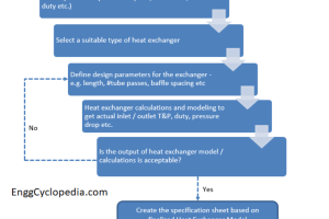
This article is a high-level tutorial on shell & tube heat exchanger design procedure. The article contains a study on finalizing the process parameters and preparing the process specification sheet for the new exchanger.
Shell and tube heat exchanger equations
In this article, we will take a detailed look at the equations required for shell and tube heat exchanger sizing calculations and design.
Shell and tube heat exchanger pressure drop
The pressure drop across a shell and tube heat exchanger is mainly a function of the heat exchanger structure and shell & tube arrangement. When you are designing a new shell & tube exchanger, you can use the pressure drop calculations to verify that the selected design satisfies your process requirement of allowable pressure drop across the exchanger.
In this article, we will take a deep look at the shell & tube heat exchanger pressure drop, why it is important, how to calculate it and what factors affect the pressure drop. Also, use these calculators to quickly calculate pressure drop in heat exchangers.