Pump sizing calculations are a critical aspect of designing any fluid handling system. Correctly sizing a pump is essential to ensure that the system operates efficiently and effectively, with minimal energy consumption and maintenance requirements. In this post, we will explore the basics of pump sizing calculations and guide you through the essential steps required to determine the flow rate, NPSH, head, and power requirements for a pump.
Table of content:
NPSH calculation
Pump Performance curves
Pump Specific Speed and Pump Suction Specific Speed
Pump power calculation
Pump affinity laws
Pump sizing calculations
NPSH calculation
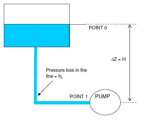
NPSH for pumps stands for Net Positive Suction Head. It is a fundamental parameter used in the evaluation of centrifugal pumps. It represents the pressure that a fluid experiences on the suction side of the pump. NPSH is a critical factor in determining the performance and reliability of a pump.
If the NPSH available (NPSHa) at pump suction falls below the required head (NPSHr), there is a risk of formation of vapor bubbles at the pump suction. Presence of vapor in the pump suction can lead to several problems such as - pump cavitation, damage to impellers, dry running of pump etc. Definition of available net positive suction head or 'NPSHA' can be found here along with a brief explanation.
Check step by step calculation of the NPSH at the pump suction using sample problem in the given post.
Pump Performance curves
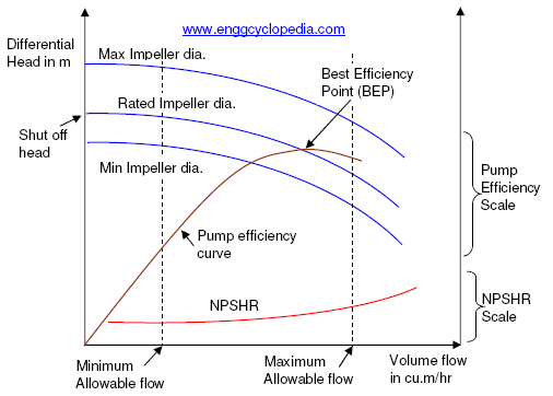
Pump performance curves are important drawings produced by the pump manufacturer. Pump performance curves are primarily used to predict the variation of the differential head across the pump, as the flow is changed. A sample pump performance curve included in this post helps to understand pump performance curves and the information that they usually provide such as variation of differential head, power requirement, NPSH requirement and pump efficiency, along with variation of operating flow.
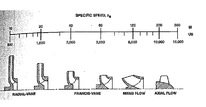
Pump Specific Speed and Pump Suction Specific Speed
Pump specific speed and pump specific speed are two quite different entities but can be confused with each other at times. This post defines both the terms with an equation for each - pump specific speed and pump suction specific speed. Difference between the two is clearly outlined.


Pump power calculation
Pump power refers to the amount of energy required by a pump to move a fluid through a system. Understanding power calculations are essential in various industries and applications, as it determines the efficiency and effectiveness of the pumping system. Properly sizing a pump and selecting the appropriate power source can help pumps to operate efficiently with minimum energy consumption and maintenance costs. Check this post to study pump power equations and calculations.
Pump affinity laws
Pump affinity laws are a set of mathematical relationships that describe how changes in shaft speed, impeller diameter, or specific gravity affect the flow rate, head, and power requirements of a centrifugal pump. These laws are important because they allow engineers and operators to predict the performance of a pump at different operating conditions, and to optimize its efficiency and reliability. By applying the pump affinity laws, it is possible to calculate the expected flow rate, head, and power consumption of a pump at a different speed or impeller diameter, without having to conduct expensive and time-consuming experiments.
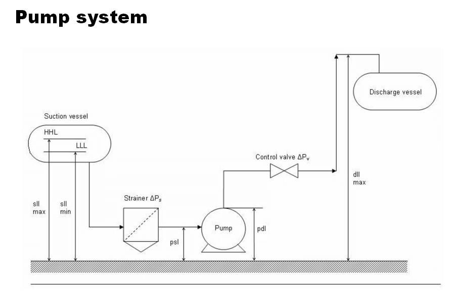
Pump sizing calculations
Problem statement
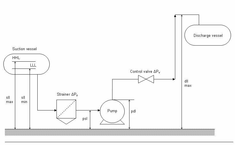
Perform pump sizing calculations to estimate the pump differential pressure, shaft power and motor power requirement to pump 200,000 kg/hr of water. The water stream is available from a storage tank which operates at atmospheric pressure and 250C.
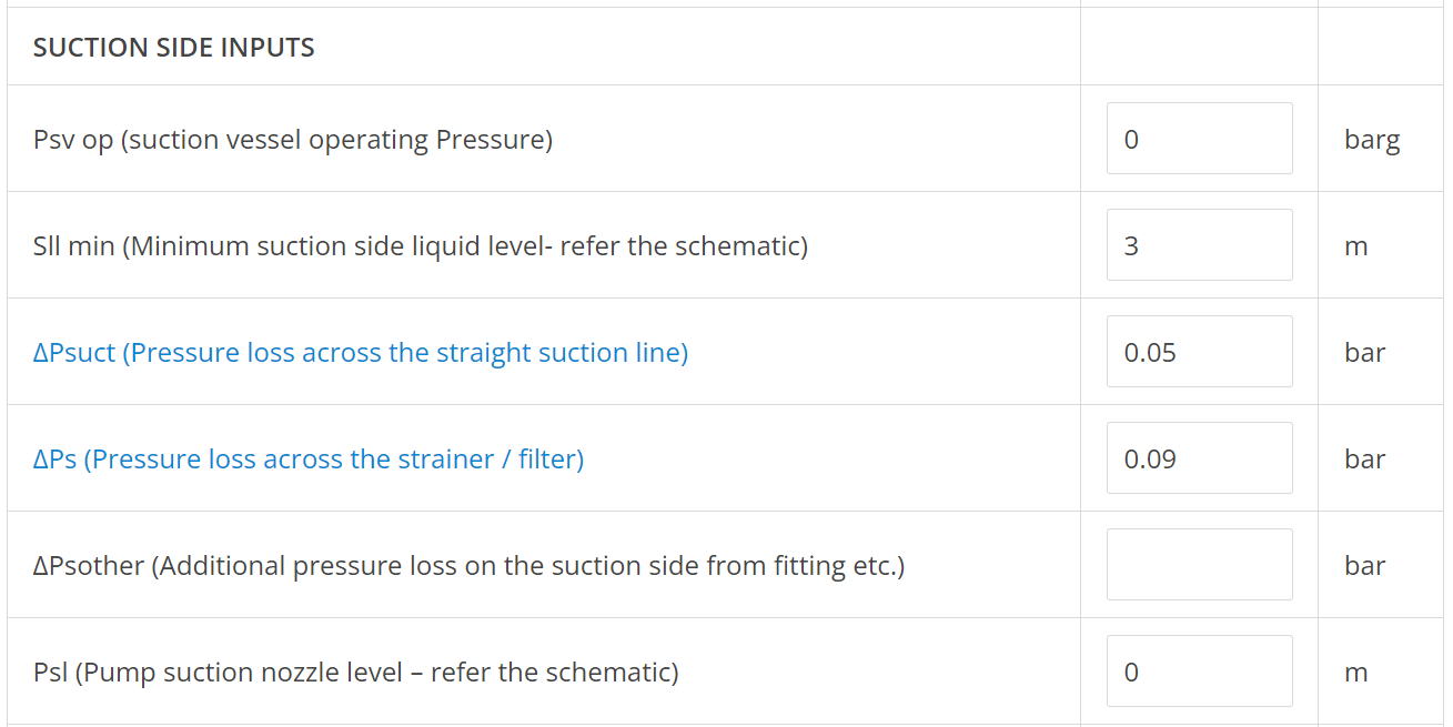
Minimum liquid level in the storage tank above pump suction nozzle is kept as 3m. Suction line is 6" in size and 10m long.
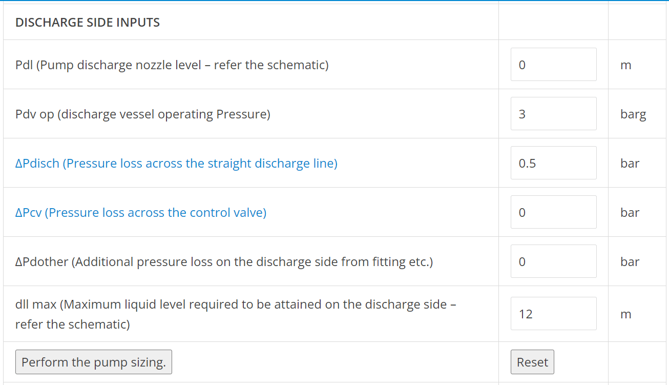
The discharge from pump is to be sent to another vessel with a top connection for water inlet. The maximum height for the 6" discharge line above the pump discharge nozzle is 12m. The discharge vessel operates at a pressure of 3 barg. There is no control valve in the discharge line. Discharge line to be assumed 100m long considering all the fittings and valves.
Assume pump efficiency to be close to 70% and motor efficiency to be close to 90%.
Solution
This sample problem is solved in following 3 basic steps. Various calculators from EnggCyclopedia are used for solving this sample problem. Check the step y step procedure given below to easily perform pump calculations.

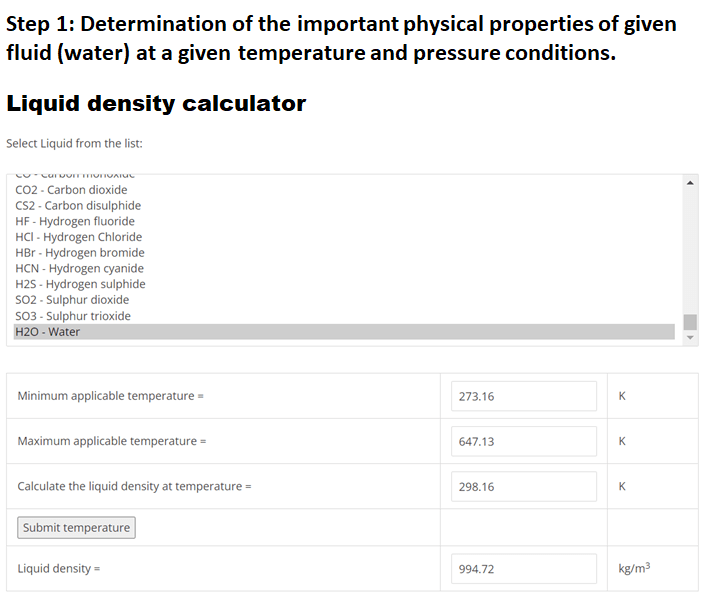
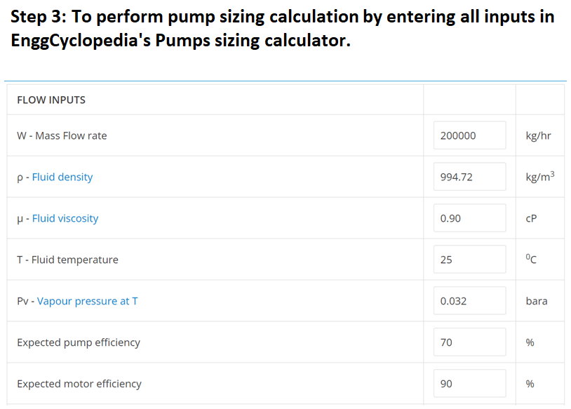
Step 1: First step of solving this sample problem requires determination of the important physical properties of given fluid (water) at given temperature and pressure conditions.
Using EnggCyclopedia’s Liquid Density Calculator, water density at 250C =994.72 kg/m3.
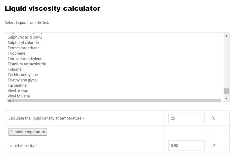
Using EnggCyclopedia’s Liquid Viscosity Calculator, water viscosity at 250C =0.90 cP.
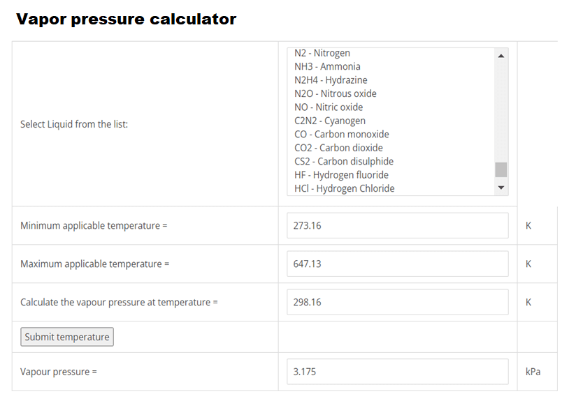
Using EnggCyclopedia’s Vapor Pressure Calculator, water vapor pressure at 250C =0.032 bara.
Step 2: Second step to solve this sample problem is to calculate various pressure drop values in the suction side. Line pressure drop is to be calculated using EnggCyclopedia's pipe pressure drop calculator. For help regarding the use of this calculator, refer to solved example for line sizing. The line pressure drop for discharge line is also to be calculated in the same way. In the present case, the pressure drop for 6" suction and discharge lines is around 5 bar/km. For 10m suction line the pressure drop becomes 0.05 bar and for 100m discharge line, it becomes 0.5 bar.
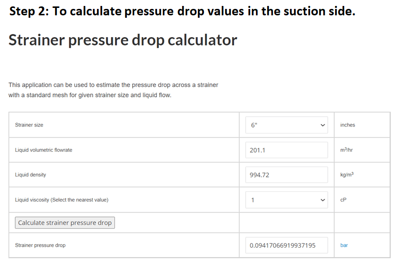
For suction line strainer, pressure drop can be calculated using EnggCyclopedia's Strainer pressure drop calculator. For this example, the strainer pressure drop is around 0.09 bar.
Step 3: All these inputs should now be entered in EnggCyclopedia's Pumps sizing calculator as the final step of pump sizing calculations. In the present example only the difference between heights of liquid level and pump suction/discharge nozzles is considered instead of considering the absolute heights. Hence the pump suction and discharge nozzles are considered as reference levels on suction and discharge sides respectively. Hence, the heights of these nozzles are considered as zero.
The given image in the above given presentation represents the calculation performed along with all the inputs and outputs.
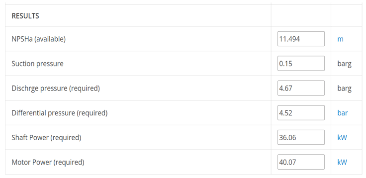
As observed from the solved sample problem, the required differential pressure is 4.52 bar. Pump shaft power and motor power requirements are 36.1 and 40.1 kW respectively. NPSHa and suction pressure values are also available for checking the suction line adequacy. A high NPSHa value (11.5m) indicates that the pump suction line and height of the liquid on suction side are adequate to run the pump.