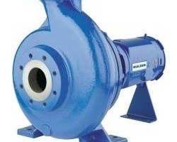
Different types of heat transfer equipment is widely used in the process industry to heat up or cool down process fluids. Out of all different types, shell and tube heat exchangers are quite popular and widely used for a variety of applications. Let's look at a typical shell & tube heat exchanger diagram to understand its structure.
Shell & tube heat exchangers
This type of heat exchangers consists of metal tubes passing through another metal enclosure, which is referred to as the 'shell'. So typically we have a fluid on shell side and anther fluid on the tube side. Heat transfer between the two fluids occurs across the tube walls.
There are many subtypes of shell and tube exchangers created by different configurations of the shell and tube arrangement. This versatility is one of the reasons why shell and tube exchangers are so popular among process design engineers.
Design of shell and tube exchangers is commonly governed by the standards created by TEMA (Tubular Exchangers Manufacturers Association).
Shell & tube heat exchanger parts
Following diagram is the structure of a TEMA style shell and tube heat exchanger. The diagram itself is based on the TEMA standards.
This diagrams illustrates all the important parts in the construction of a shell & tube heat exchanger, as per the TEMA standards. It also gives you the exact correct nomenclature for each of those parts. For further details you can refer to the relevant TEMA guidelines.
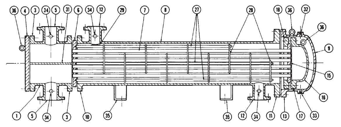
- Stationary head - channel
- Stationary head - bonnet
- Stationary head flange - channel or bonnet
- Channel cover
- Stationary head nozzle
- Stationary tubesheet
- Tubes
- Shell
- Shell cover
- Shell flange - stationary head end
- Shell flange - rear head end
- Shell nozzle
- Shell cover flange
- Expansion joint
- Floating tube sheet
- Floating head cover
- Floating head flange
- Floating head backing device
- Split shear ring
- Slip-on backing flange
- Floating head cover - external
- Floating tubesheet skirt
- Packing box flange
- Packing
- Packing gland
- Lantern ring
- Tie rods and spacers
- Transverse baffles or support plates
- Impingement plate
- Longitudinal baffle
- Pass partition
- Vent connection
- Drain connection
- Instrument connection
- Support saddle
- Lifting lug
- Support bracket
- Weir
- Liquid level connection
The exchanger shown in this diagram is a floating head type shell & tube exchanger. To check details of all parts check this post.
Shell & tube heat exchanger classification diagram
Another important diagram from the TEMA standards is actually a table that helps us classifying different types of shell and tube exchangers and correctly identifying their nomenclature.
TEMA standards describe these various components in detail. A shell & tube heat exchanger (STHE) is divided into three parts:
- The front end
- Shell
- Rear end
Following table from the TEMA standards explains the different possible configurations for each of the 3 broad parts.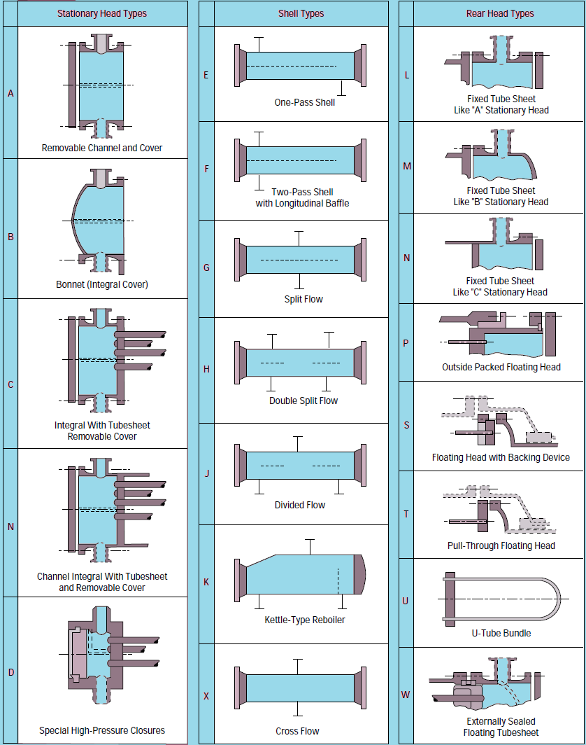
Typical P&ID for shell & tube exchangers
Apart from the internal structure, another important diagram for heat exchanger design, is the piping & instrumentation diagram or P&ID for heat exchanger.
Following diagram is a typical P&ID arrangement for a shell & tube heat exchanger.
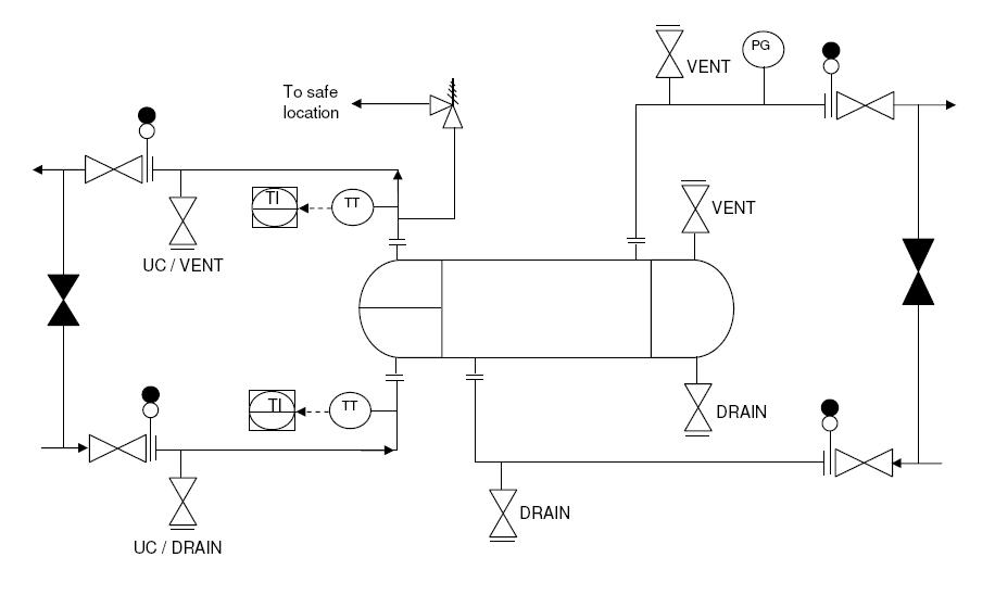
This post explains the guidelines for creating a detailed P&ID diagram for a shell and tube exchanger.