It is very important to understand the shell and tube heat exchanger P&ID diagram. Because shell and tube heat exchangers are the most widely used heat exchangers in process industries. P&ID diagram plays a critical role in ensuring the safe, efficient, and effective operation of a shell and tube heat exchanger.
A P&ID (Process and Instrumentation) diagram is a detailed technical illustration that is used to document and represent a process system. P&ID diagrams are essential for the design, operation, and maintenance of any type of heat exchanger.
Table of content:
Typical shell & tube heat exchanger P&ID diagram
Importance of P&ID diagram of shell and tube heat exchangers
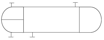
Typical shell & tube heat exchanger P&ID diagram

This shell & tube heat exchanger diagram is actually a simplified P&ID, depicting typical arrangement of piping, instrumentation and control systems around a shell & tube exchanger. This P&ID arrangement is a generic arrangement irrespective of the type of shell & tube exchanger used.
Determine Fluid allocation
Determine which fluid would go to the shell side and which to the tube side. This will pave the way for rest of the design.
Each time when you design for a new shell and tube heat exchanger, you will need to decide where the hot / cold fluid streams must be places. Which should go through shellside and which will go through the tubes. This decision is commonly referred to as fluid allocation for the shell & tube heat exchanger.
Required heat transfer rate considering optimum equipment cost, Least maintenance, and minimum pressure drop are the factors need to be consider to decide the fluid allocation. Follow the guidelines given in shell and tube heat exchanger design procedure post to select shell side and tube side fluid.
Select equipment symbol
Proper equipment symbol should be selected first of all, as shown in the presented drawing. This should be selected from the list of equipment symbols on the legend sheets of a particular project.
The specific symbol used can vary based on industry standards and specific software or guidelines used to create the P&ID diagram.
Representation of Nozzles
All the nozzles on the exchanger should then be correctly represented with size and flanges. This includes inlet and outlet nozzles, drains, vents, utility connections etc.
Inlet and outlet lines
Inlet and outlet lines are the next to be drawn up. Line number, material class, size etc. is to be correctly assigned to each of the lines. If the unit is envisaged to be in operation while the exchanger is under maintenance, then bypass lines should be drawn up on shellside, tubeside or on both sides as shown in the drawing presented here.
Isolation valves
Isolation valves, spectacle blinds, spacers etc. to be used for maintenance should be drawn up next on the inlet / outlet lines. Bypass lines to be fitted with normally closed isolation valves.
Thermal relief valve
Thermal relief valve should be provided where required. Generally thermal relief valves are required on the cold liquid streams, when there is a possibility of blockage in the heating medium on the other side of exchanger. In case of such blockage, there is possibility of overheating the cold stream and hence requirement for thermal relief valve. Discharge of a relief valve to be routed to an appropriate, safe location.
Drains and Vents
Drains and vents to be provided on both sides of the exchanger (hot and cold sides), either on the exchanger itself or inlet / outlet piping, so that the equipment can be completely drained for maintenance.
Utility connections
For fouling service on the tubeside, utility connections should be provided as indicated in the presented drawing, for cleaning purpose.
Temperature and Pressure Gauges
Temperature and pressure gauges and transmitters to be provided as per requirements for operating and controlling the equipment. Normally temperature monitoring is required for the process side of the heat exchanger. Also generally temperature control is implemented on the process side of the exchanger.
All the guidelines given here are very general and may be modified as per specific requirements of any particular project.
Importance of P&ID diagram of shell & tube heat exchangers
P&ID (Process and Instrumentation Diagram) diagrams are essential for the design, operation, and maintenance of any type of heat exchanger. They provide a visual representation of the heat exchanger and help to ensure that all relevant information is easily accessible and understandable. Here are some of the reasons why P&ID diagrams are important for shell & tube heat exchangers:
- Design and Engineering: It help engineers and designers understand the flow patterns and fluid interactions in the heat exchanger. Accurate P&ID diagrams can ensure that the heat exchanger is correctly sized for the process conditions, including the fluid flow rate, temperature, and pressure.
- Process Optimization: P&ID diagrams can be used to optimize the performance of the heat exchanger by identifying areas of potential improvement in fluid flow, temperature control, and energy efficiency.
- Maintenance and Troubleshooting: P&ID diagrams provide critical information for maintenance and troubleshooting, including the location and type of components, fluid types and flow patterns, and instrumentation and control systems. Accurate P&ID diagrams provide a visual representation of the process system, making it easier to identify problems and plan corrective action. This can result in reduced downtime and increased process efficiency.
- Compliance: P&ID diagrams are often required by industry regulations and standards to ensure that the heat exchanger meets specific safety, performance, and environmental requirements.
Related resources and references
- This is another detailed diagram of a shell & tube exchanger, which lists all its parts with their TEMA nomenclature.
- Typical specification sheet for a shell & tube heat exchanger
- Detailed guidelines for shell & tube exchanger design procedure
- A list of calculators and tutorials useful for heat exchanger design calculations