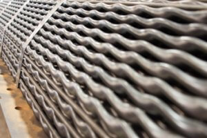
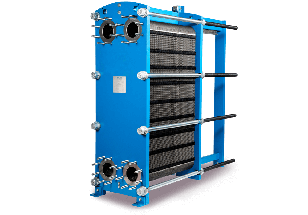
The plate and frame heat exchanger consists of a series of rectangular parallel plates. These plates are arranged in a frame and are pressed together to form a series of channels for the flow of fluid through it. Plates are separated by gaskets and have corrugated faces, which provide a high degree of turbulence.
It has inlet and outlet nozzles at the end. Hot fluid passes through the alternate pairs of plates which transfer heat to the plates, eventually, heat is transferred to the cold fluids in the adjacent plates. These exchangers provide a high heat transfer area which results in a high heat transfer rate with low-temperature differences as well.
Table of content
How do plate and frame heat exchangers work?
Plate and Frame Heat Exchanger Sizing
Cleaning & Maintenance of Plate and Frame Heat Exchanger
How do plate and frame heat exchangers work?
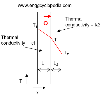
A plate and frame heat exchanger works by allowing two different fluids to flow through separate channels, with the heat being transferred from one fluid to the other through the metal plates. The fluids are typically separated by a gasket, which forms a seal between the plates, creating two separate flow channels. Due to the temperature difference between two fluids and thermal conductivity of the metal heat transfer takes place.
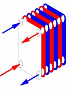
The heat transfer process in plate and frame heat exchanger is as follows:
- The hot fluid flows through one set of channels on one side of the plates. The hot fluid transfers heat to the plates through conduction.
- The cold fluid flows through the other set of channels on the opposite side of the plates. The cold fluid absorbs heat from the plates through conduction.
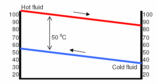
- As the hot fluid flows through the heat exchanger, it loses some of its heat to the cold fluid. This causes the temperature of the hot fluid to decrease, and the temperature of the cold fluid to increase.
- The heat transfer process continues until the temperature of the hot fluid reaches equilibrium with the cold fluid.
The heat exchanger working principle has been discussed thoroughly here.
Plate and Frame Heat Exchanger Sizing
Sizing a plate and frame heat exchanger involves selecting the appropriate size and number of plates, determining the correct flow rates and pressure drops for the fluids, and selecting the appropriate materials for the plates, gaskets, and frame.
The first step in the design of a plate and frame heat exchanger is to determine the maximum amount of heat that needs to be transferred and the desired temperature difference between the fluids. This calculated heat duty and the temperature difference will be used to determine the size and number of plates required.
Fluid properties, inlet/outlet temperature of fluids, the inlet pressure of fluids, and allowable pressure drop must be defined to size a plate and frame heat exchanger. The fluids should be flowing through the heat exchanger at the correct flow rates to ensure optimal heat transfer and to prevent any damage to the heat exchanger. The pressure drops across the heat exchanger also need to be within acceptable limits to prevent any damage to the heat exchanger.
We can calculate the number of plates required by using, N =S/s
Where, N = Number of plates required
S = Total heat exchanger area (m2)
s = size of the single plate (m2)
The plates are typically made of stainless steel or other high-grade metals that are resistant to corrosion. Gaskets are made of materials such as rubber, silicone, or PTFE, and are chosen based on their chemical compatibility with the fluids. The frame is typically made of steel so that it can withstand the pressure of the fluids.
It is required to go into detail about the many options available for the plates and use correlations that will allow us to recalculate the overall heat transfer coefficient and then a required exchange area. The calculation will then be iterative until the calculated heat exchange area is equal to the assumed area.
This is the detailed design procedure for the heat exchanger design.
Finally, the inlet and outlet connections and flow distribution devices need to be designed. The inlet and outlet connections can be made of various materials such as copper, steel, or plastic. The flow distribution device can be a simple pipe or a more complex system of nozzles, to ensure that the fluid flows evenly across the heat exchanger.
Effects of fouling must be taken into account and the fouling factor must be calculated accurately for the adequate design of the plate and frame heat exchanger.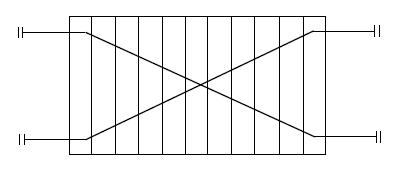 This is the p&id symbol of plate and frame heat exchangers used in process industries.
Cleaning & Maintenance of Plate and Frame Heat Exchanger
To maintain high a heat transfer area, it is necessary to keep the heat exchanger clean, as buildup or deposits on the plates can reduce the heat transfer area and decrease the efficiency of the heat exchanger. The cleaning process will depend on the type of fluids and the degree of fouling or buildup on the plates and gaskets. Here are a few cleaning methods discussed for plate and frame heat exchangers:
Chemical Cleaning
Chemical cleaning of plate and frame heat exchangers involves circulating a specialized descaler, such as acid or alkali, to remove any buildup or deposits on the plates and frames. The descaler is circulated through the heat exchanger and allowed to soak for some time to loosen and remove the buildup. After cleaning, the heat exchanger is flushed with water to remove any remaining cleaning solution and debris.
It is important to use appropriate chemicals for chemical cleaning as some chemicals may be corrosive to the metal. Nitric acid, Sulfuric acid, Citric acid, Phosphoric acid, EDTA, etc chemicals are used for chemical cleaning.
Mechanical Cleaning
Mechanical cleaning involves opening up the heat exchanger unit and using synthetic bristle brushes, high-pressure water spray, and other specialized tools to mechanically wash the plates.
The manual method involves using a brush or scraper to remove dirt, debris, and buildup from the plates and gaskets. This method is typically used for heat exchangers that have a light amount of fouling or for heat exchangers that are difficult to access. This method is typically used for heat exchangers that have a light amount.
The automated method involves the use of a high-pressure water jet machine. A high-pressure water jet is used to remove the dirt, debris, and buildup from plates and gaskets. This method is typically used for heat exchangers that have a moderate amount of fouling.