The refrigeration cycle is a crucial component in the operation of a heat pump. Without it, a heat pump would not be able to transfer heat from one location to another, which is the fundamental principle of how a heat pump works. The heat pump refrigeration cycle enables the heat pump to transfer heat from one location to another. This is done by circulating refrigerant through a series of components (compressor, condenser, expansion valve, and evaporator) that alternately absorb and release heat.
Table of content:
Heat pump vs Refrigeration cycle
Heat pump cycle
Refrigeration cycle
Refrigeration cycle TS diagram
Heat pump vs Refrigeration cycle
In basic terms, both the refrigeration cycle and heat pump operate similarly by pumping heat against its natural direction. However, they have different applications. The refrigeration cycle is used to create a cooling effect in a confined space, while the heat pump is used to transfer heat from one location to another for heating or cooling purposes.
To explain it visually, both refrigeration cycle and heat pump can be imagined as a box with electrical input, where one side gets cold (heat flows inside the box) and the other side gets warm (heat flows out of the box). Depending on the intended use, the cold or hot side is utilized. For instance, in a refrigerator, the cold side cools the interior, while in a heat pump, the hot side heats the water.
However, in both cases, external energy is required to operate the process. The difference between the two is the location of the hot or cold side. In a refrigerator, the warm side is on the backside, which gives off heat to the surrounding environment. In heat pump, the cold side is outside and absorbs heat from the environment.
Heat pump cycle
The heat pump cycle is a process that allows heat pumps to transfer heat from one location to another using a refrigerant that circulates through four main components: compressor, condenser, expansion valve, and evaporator. Here is a brief overview of each component and its role in the cycle:
- Compressor: The compressor is the heart of the heat pump refrigeration cycle. It pressurizes and circulates the refrigerant throughout the system.
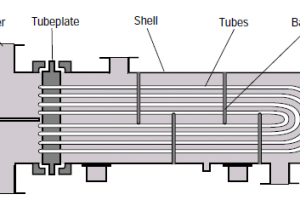
- Condenser: The condenser is responsible for transferring the heat absorbed from the evaporator to the environment, typically through a heat exchanger.
- Expansion valve: The expansion valve is a throttling device that controls the flow of refrigerant to the evaporator, reducing its pressure and causing it to expand.
- Evaporator: The evaporator is where the refrigerant absorbs heat from the surrounding environment, typically indoor air or water.
Refrigeration cycle
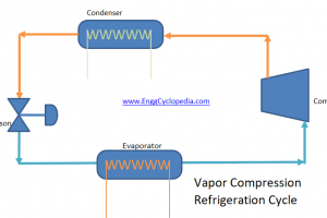
The refrigeration cycle is a process that cools a space or substance by removing heat from it and dissipating it to the surrounding environment. The cycle consists of four main stages, each involving a change in pressure and temperature. Here's an example of a refrigeration cycle diagram:
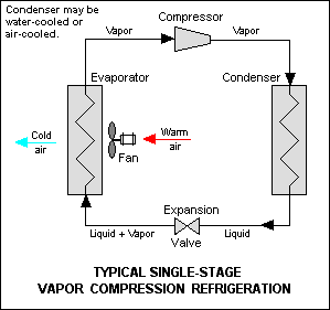
Here is a step-by-step guide to the refrigeration cycle:
- Compression: The refrigerant gas enters the compressor in a low-pressure, low-temperature state. The compressor then compresses the gas, raising its temperature and pressure.
- Condensation: The compressed gas then enters the condenser, where it is cooled by a heat transfer process and condenses into a high-pressure, high-temperature liquid.
- Expansion: The high-pressure liquid then enters the expansion valve, which reduces its pressure and causes it to expand. This expansion causes the liquid to evaporate, changing it back to a gas.
- Evaporation: The low-pressure gas then enters the evaporator, where it absorbs heat from the surrounding environment, causing it to cool. The refrigerant then returns to the compressor, and the cycle begins again.
Refrigeration cycle TS diagram
A Temperature-Entropy (T-S) diagram is a useful tool to visualize the refrigeration cycle. The T-S diagram plots temperature on the vertical axis and entropy on the horizontal axis. The T-S diagram for the refrigeration cycle is shown below.
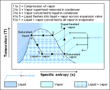
Here is a brief explanation of each stage of the refrigeration cycle on the T-S diagram:
- Compression: The refrigerant gas is compressed in the compressor, which raises the temperature and pressure. This process is represented by the line segment from point 1 to point 2, which is a vertical line indicating a constant entropy process.
- Condensation: Condensation process is represented by the line segment from point 2 to point 3, which is a horizontal line indicating a constant temperature process.
- Expansion: Expansion causes the liquid to evaporate, changing it back to a gas. This process is represented by the line segment from point 3 to point 4, which is a vertical line indicating a constant entropy process.
- Evaporation: Evaporation is represented by the line segment from point 4 to point 1, which is a horizontal line indicating a constant temperature process.